
Search for answers or browse our knowledge base.
Retro C Saw Head Vibration and Humming Diagnosis
A vibrating or humming saw head is commonly caused by contact at the encoder guard or by looseness and misalignment in the blade-brake assembly. Stop the machine if the noise is new, severe, accompanied by heat, or associated with unstable blade or head movement.
Safety: Lock out the saw before touching guards, brakes, the hub, or the blade area. Remove the blade when working around the brake assembly. Any powered diagnostic test must be brief, controlled, and performed only after all personnel, tools, and temporary test material are clear of moving parts.
Cause 1: Encoder guard contact
The encoder guard plate can vibrate where two metal surfaces touch. With the saw locked out, inspect the location shown below for witness marks, looseness, or metal-to-metal contact.
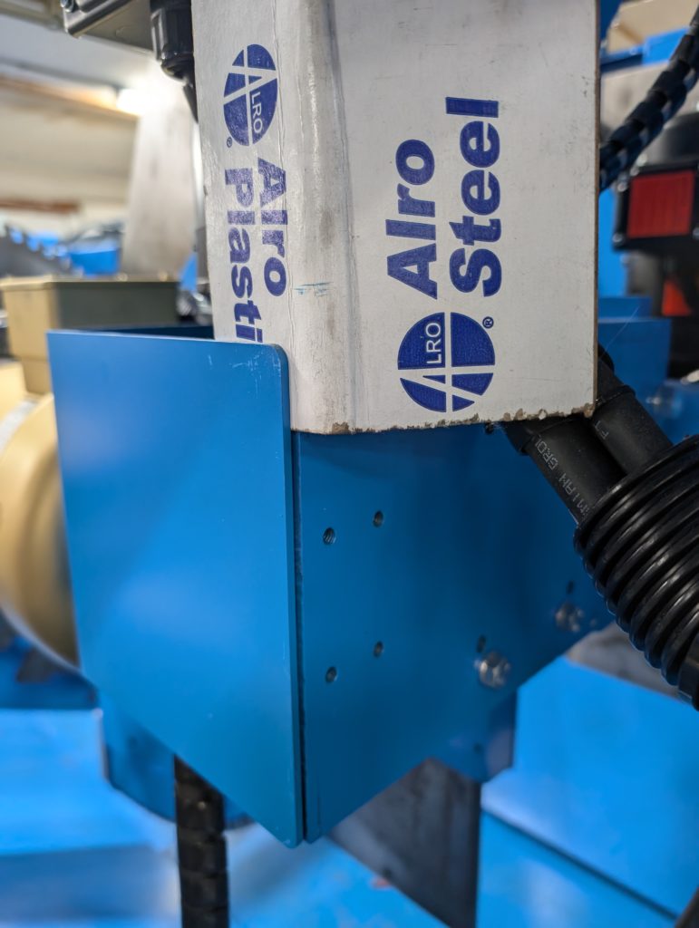
- With power locked out, place a thin piece of paper or cardboard between the suspected guard surfaces only as a temporary diagnostic separator.
- Clear personnel and tools, then perform a brief controlled manual motor test.
- If the noise disappears, stop and lock out the saw again. Remove the temporary paper or cardboard.
- Correct the guard alignment or fastening so the metal surfaces do not vibrate together. Never leave the temporary separator installed for production.
Cause 2: Blade-brake hardware
If the guard is not the source, remove the blade and inspect the brake assembly with the machine locked out.
Caliper connecting-pin set screw: Confirm that the small set screw shown below is tight and correctly tensions the brake-caliper connecting pin.
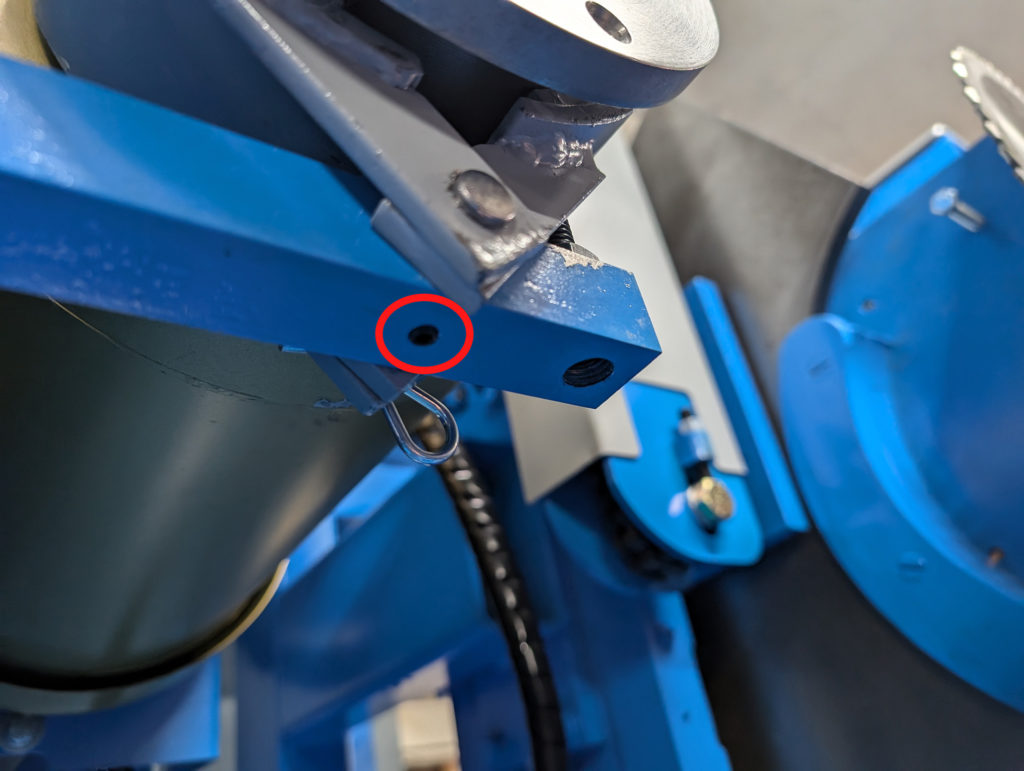
Return spring: Confirm that the spring returns the left caliper away from the hub. Replace a damaged, weak, or permanently deformed spring rather than repeatedly stretching it.
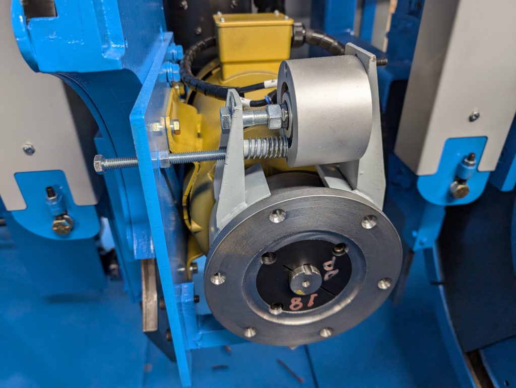
Caliper clearance and timing: Adjust the left and right calipers so they contact the hub at the same time when engaged. With the machine locked out and the brake released, rotate the hub by hand and confirm that both calipers are centered and as close as practical without rubbing. Use the long bolt and locknut for the left side and the adjustment shown below for the right side.
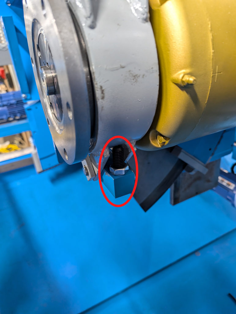
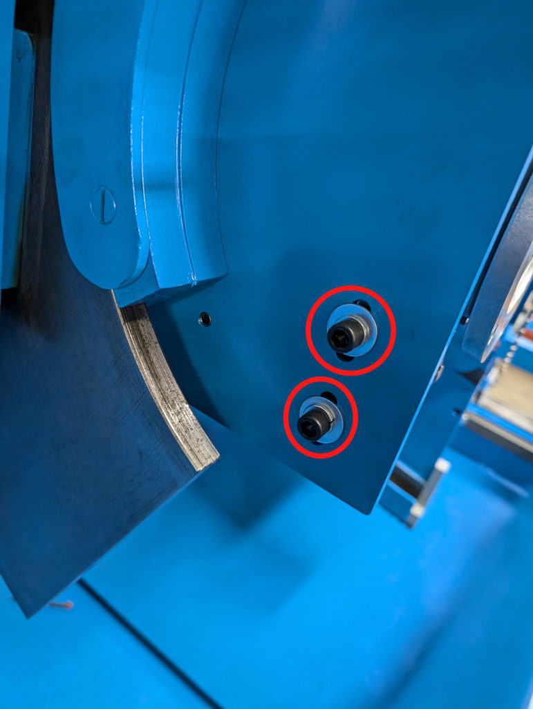
Adjustable brake-support arm: On newer saws with Y-axis adjustment in the support arm, confirm that the Allen screws shown below are tight and that the support has not shifted.
Reassemble and verify
- Confirm that the hub turns freely with the brake released and that both calipers clear the hub evenly.
- Engage the brake and confirm that both calipers contact together.
- Reinstall the blade and every guard using the approved procedure.
- Remove tools and temporary test material, then clear personnel from the area.
- Run a brief low-speed manual test, followed by a normal stop. Confirm that the vibration is gone and the brake operates normally.
If the noise remains, record when it occurs, which head is affected, whether it changes with speed, and whether the brake is engaged. Contact Enventek Support before making further alignment or structural adjustments.
Escalate When
Record the exact screen message, affected component, indicator-light state, and steps already attempted. Contact Enventek Technical Support if the fault remains or the machine does not respond as expected.