Search for answers or browse our knowledge base.
“Crossup Detected” Light Sensor Troubleshooting and Adjustment
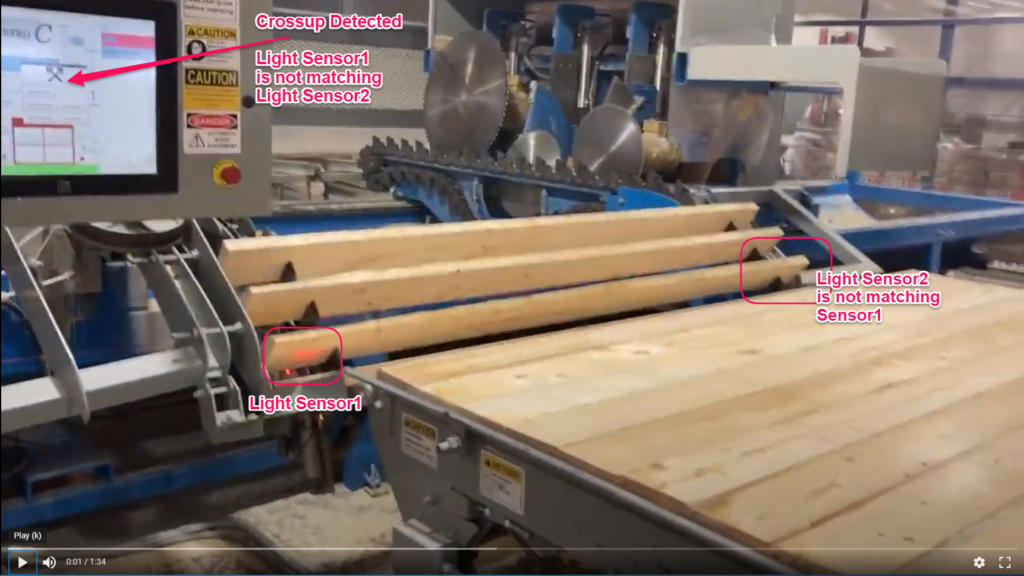
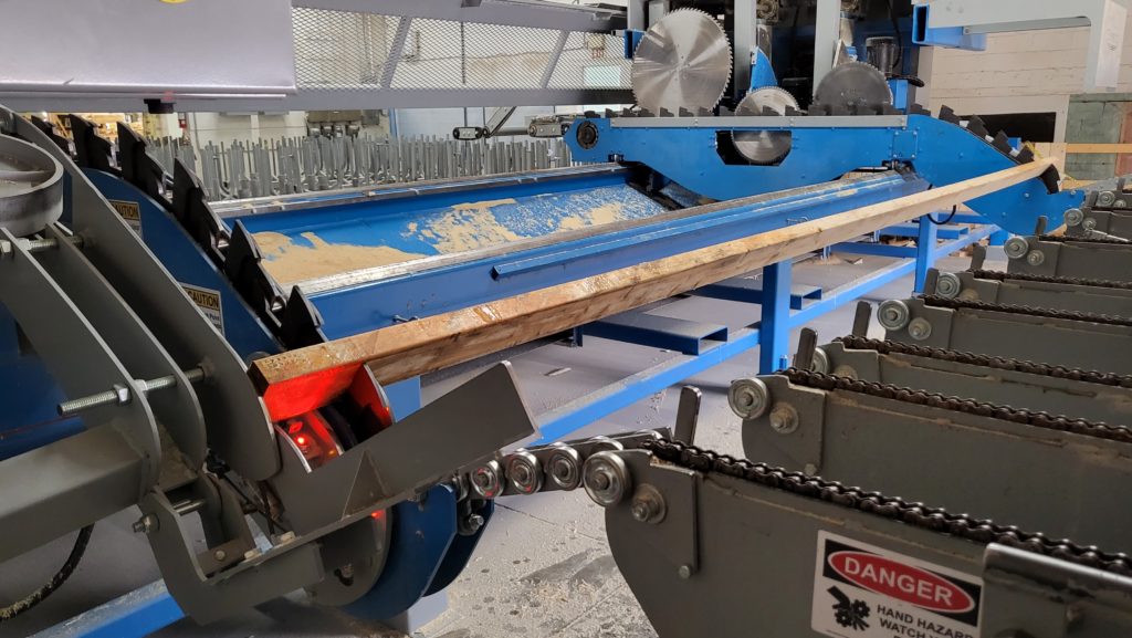
The Retro C is equipped with sensors that are constantly detecting the position of the lumber as it is loaded onto the material feed arms. As lumber passes by the sensors they measure the position of the board on each side to make sure that the board is not crossed up.
If Light Sensor1 and Light Sensor2 do not match, a “Crossup Detected” popup will pause feeding. USE E-STOP when wiping saw dust film/cloud off of the light sensors as part of saw shift startup – remember to wipe the far side carriage Sensor2 (sometimes if Sensor1 is clean but Sensor2 is still dirty this will give crossup errors)
WARNING: IF E-STOP is not used and AUTO MODE is on, the saw will start when Sensor1 is wiped thinking a board has been dropped USE E-STOP WHEN WIPING SENSORS
Summary
Most of the time, if you receive more lumber cross-up warnings than you think you should, it’s because you have seen dust covering some or most of the sensors. If that isn’t the case it is likely one of these reasons 1) The sensor has been hit and rotated out of position/alignment 2) The sensor’s sensitivity is not set right. 3) One or both of the sensors have a bad cable. Most of the time the issue is cleaning the sensor or alignment of the sensor so focus on those issues before continuing.
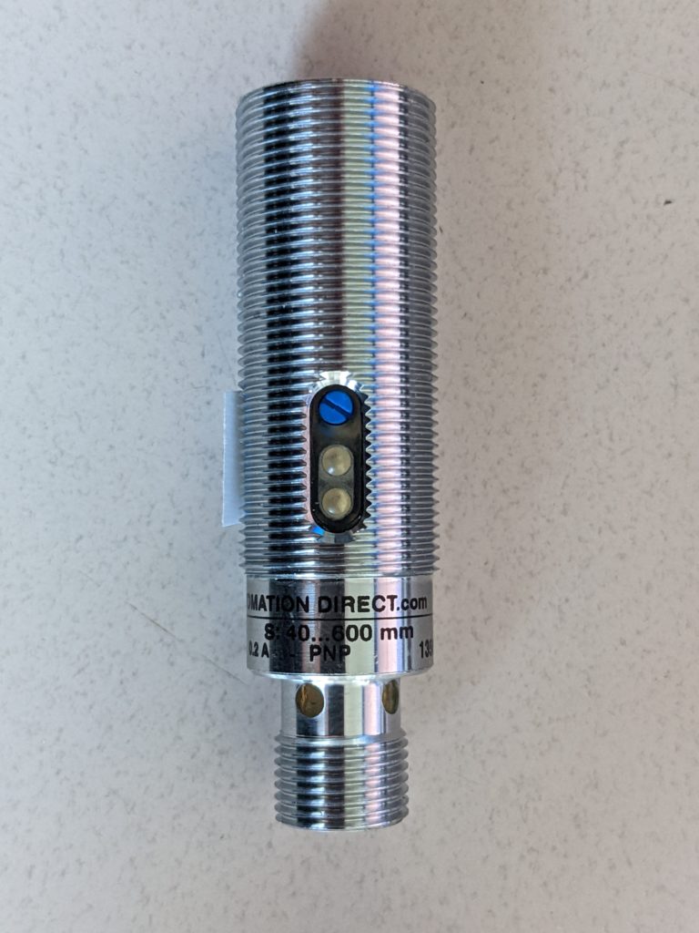
Images of sensor locations
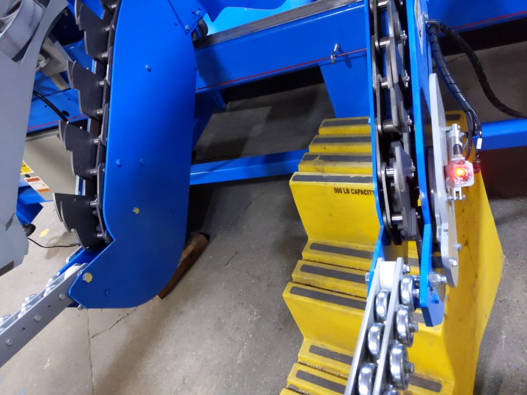
In the image below the sensor with the issue is the one in the center of the picture and it is located on the stationary side of the saw.
On the stationary side material feed arm, the cross-up sensor is the upper sensor of the two, on the carriage side it is the only sensor.
Instructions
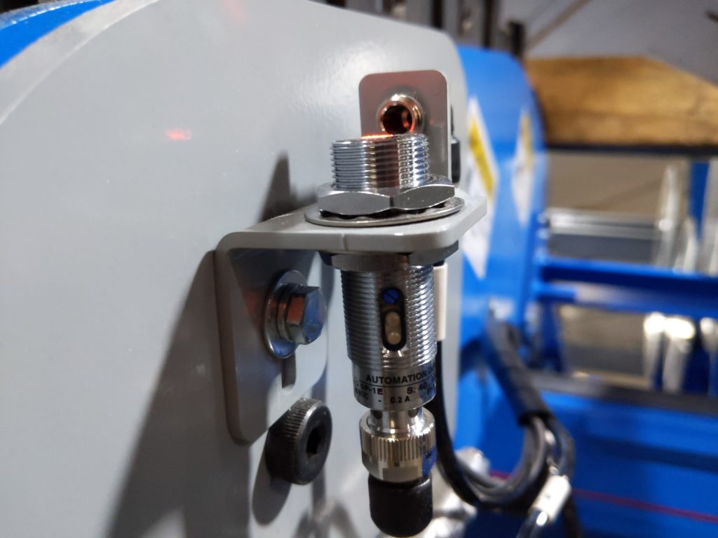
- The first step is to make sure that there is nothing like sawdust on the sensors. Take a towel and wipe off the sensors.
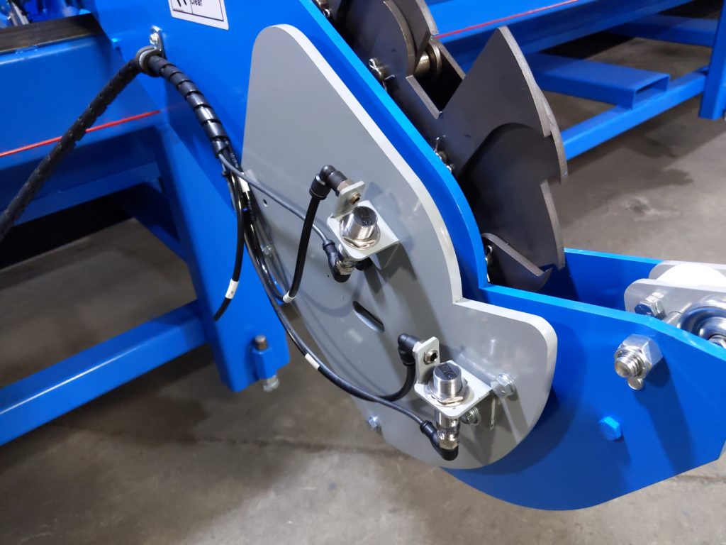
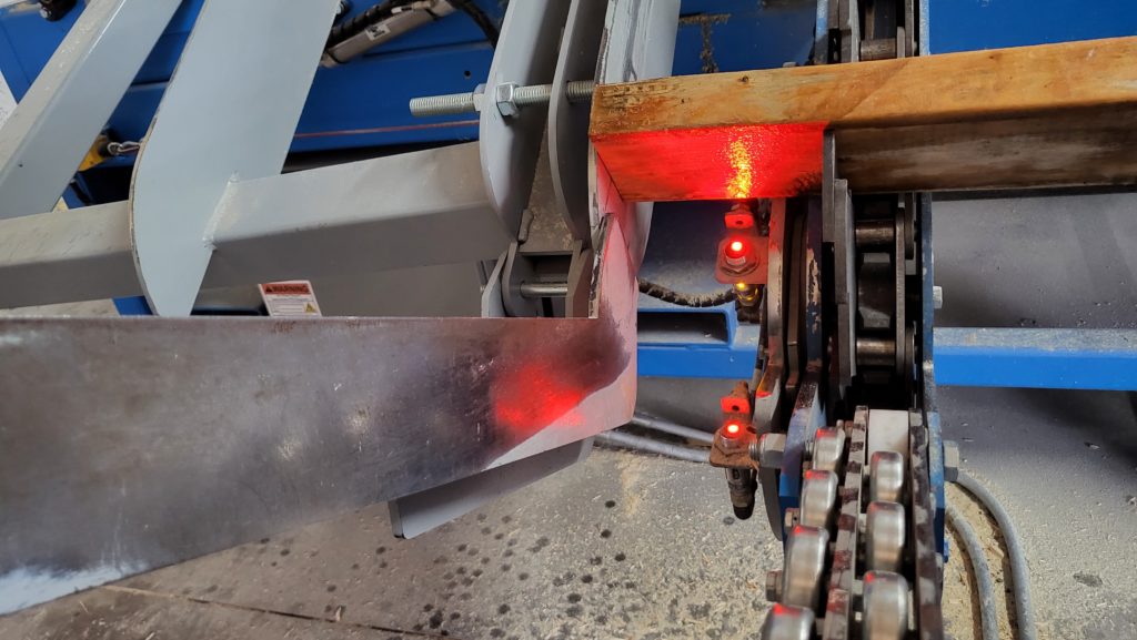
- If step 1 doesn’t solve the problem then the sensors need to be aligned so that the lumber passes over both sensors on both sides at the same time. Adjustment is done with a single bolt that holds the sensor in place. See the below picture for the bolt that allows the sensor to twist.
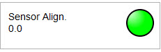
In order to tell if the sensors are aligned the operator must load a piece of lumber into the saw and let it run past the sensors. At the same time, the lumber passes the sensors the “check” screen will display how closely the sensors are aligned. The goal is to get the sensor alignment readout to be as close to zero as possible. It will likely never be zero (as shown in the image below) unless the software has recently been restarted. The goal is to be within 0.30 of zero. I.E. 0.3 or less or -0.3 or greater.
Using a straight board – Calibrate Sensor1 and Sensor2 to get the same image Rotate/twist Sensor1 and Sensor2 accordingly and then tighten
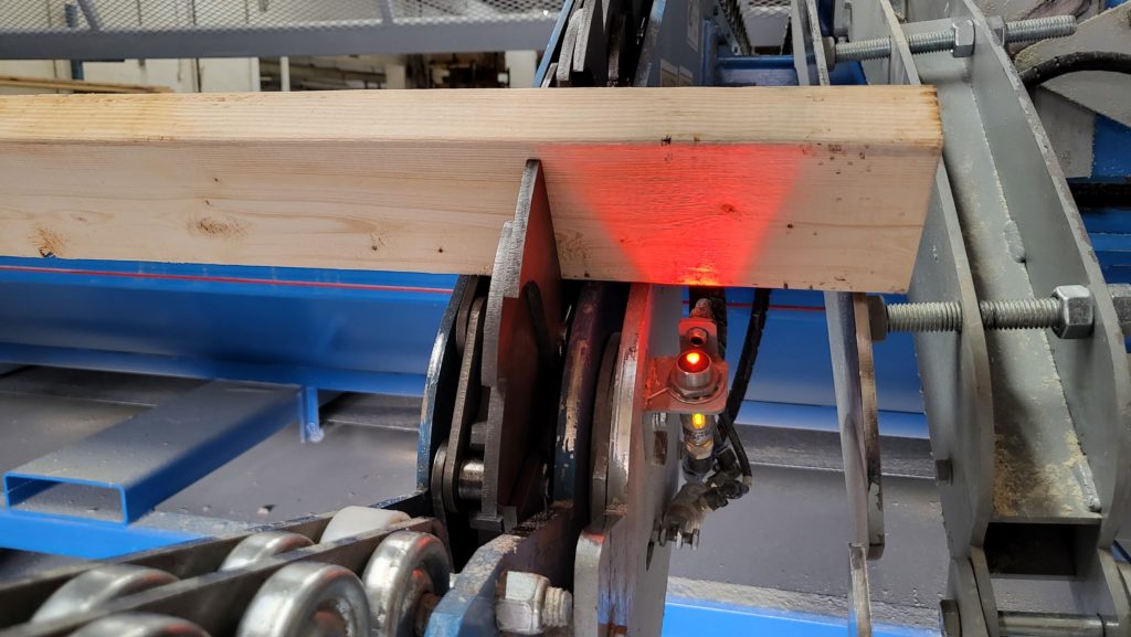
- If steps 1 and 2 are not working well the last item would be the sensitivity of the sensor can be turned up or down. That can be done by turning the blue dial on the sensor. Most likely one of the sensors needs its sensitivity turned down (counterclockwise) on the dial.
- If all else fails one of your sensors or the cable might be failing. First start with replacing the sensor and then the cable. Most of the time the sensor will fail prior to the cable.