How Can We Help?
Search for answers or browse our knowledge base.
-
Retro C
-
-
- Articles coming soon
-
- How to Replace the Retro C's Computer
- Configuring the Touchscreen Computer's "Power-On"
- How to replace micro USB on the display computers
- How To: Transfer Files to the Retro C
- How to replace the USB hard drive on the touch screen computer
- New computer set bios power on
- Old computer set bios to power on
- TouchScreen Flip / Mirror Issue
-
-
-
- Stuck Angle or Centerline - How to Recover & Recalibrate
- Replacing an Angle Encoder
- Angle movements over run when going to position.
- Angle (Arch) Movements - Overview
- Angle Chains - Proper Chain Tension
- Diagnosing Unknown Noises Coming from Blade Motor
- Pivot Point Check
- Power or Wiring Troubleshooting for Angle Motors or VFDs
- Dirty Slide
-
- Stuck Angle or Centerline - How to Recover & Recalibrate
- How To: Calibrate Centerline 1-5
- How To: Calibrate Centerline 1-5 (Advanced)
- Centerline (Vertical) Movements - Overview
- Replacing a Centerline Encoder
- Replacing a Centerline Gearbox
- Checking the Centerline Maximum & Minimum (Max & Min) Height Setting
- How to Tighten the Centerline Slides
- How To: Tension The Centerline Chains
-
-
-
- Common Retro C issues and solutions
- Countdown Timer / E-Stop Troubleshooting
- Scrap Belt or Scrap Incline VFD Disconnected: Troubleshooting
- Stuck Angle or Centerline - How to Recover & Recalibrate
- TouchScreen Flip / Mirror Issue
- Troubleshooting: Encoder Unplugged Error
- Troubleshooting: The Stationary or Carriage Side Horizontals Won't Move Anymore
-
-
Linear Pickline
-
Plant One Projection
-
SmartConveyor
-
Sticker Printer
< All Topics
Print
Pneumatic System Overview
Updated
The Pneumatic system consists of all of the air-actuated valves.
- The blade brakes – all 5 contain air cylinders for safety during an e-stop event.
- The Lumber Stops – Both sides use air brakes.
- The Carriage – Moving the Carriage ut air brakes.
The Retro C has 6 air valves, three on the stationary side and three on the carriage side.
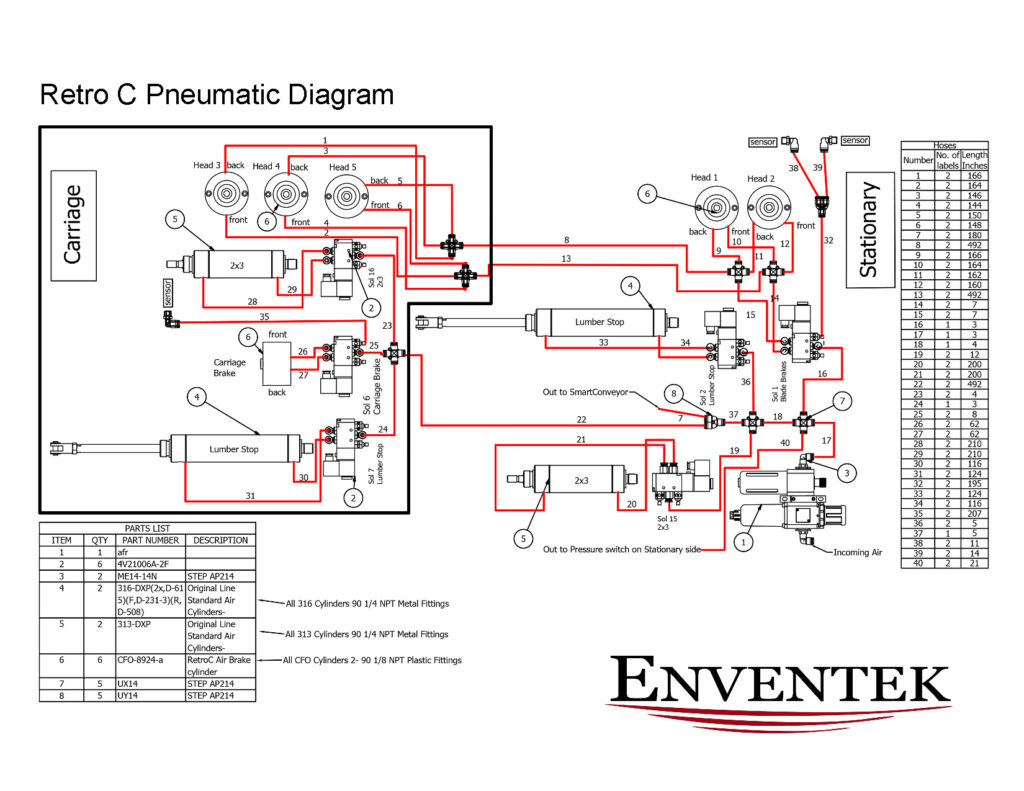
The pneumatic system controls are situated in two locations. The first location is on the back side of the saw, specifically on the stationary side. Recently we updated our cable routing and revised the placement of our solenoids the two images below represent the old and new placement of the pneumatics on the stationary side.
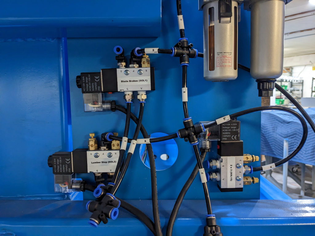
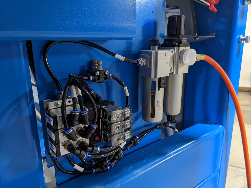
Solenoid Diagnostics
Solenoids Components
- The Electrical connector, which contains an led to see if there is a signal from the computer system. The led turns on when the computer tells the valve to fire. The valves we use are spring return so when power is removed they spring back to a default state.
- The Coil, which is 24v,120VAC, or 240VAC depending on the location and usage. At times coils can burn out. In order to diagnose a bad coil. First, check if the led light turns on/off with the computer. Second when the led light is off press the manual override on the valve body. If the valve fires and the light turns on/off the coil is bad. If the manual override doesn’t work then it could be the valve body, a jammed cylinder, or a crimped pneumatic hose.
- The Valve Body, with the inputs and outputs. The Valve body contains a red button in order to manually test the valve if the coil is off. The red button can be pressed in for a momentary test or the button can be pressed in and twisted and be held “on” while testing. The button is shown in the image below.
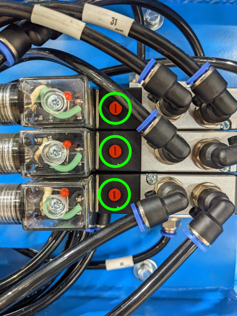
Table of Contents