How Can We Help?
Search for answers or browse our knowledge base.
-
Retro C
-
-
- Articles coming soon
-
- How to Replace the Retro C's Computer
- Configuring the Touchscreen Computer's "Power-On"
- How to replace micro USB on the display computers
- How To: Transfer Files to the Retro C
- How to replace the USB hard drive on the touch screen computer
- New computer set bios power on
- Old computer set bios to power on
- TouchScreen Flip / Mirror Issue
-
-
-
- Stuck Angle or Centerline - How to Recover & Recalibrate
- Replacing an Angle Encoder
- Angle movements over run when going to position.
- Angle (Arch) Movements - Overview
- Angle Chains - Proper Chain Tension
- Diagnosing Unknown Noises Coming from Blade Motor
- Pivot Point Check
- Power or Wiring Troubleshooting for Angle Motors or VFDs
- Dirty Slide
-
- Stuck Angle or Centerline - How to Recover & Recalibrate
- How To: Calibrate Centerline 1-5
- How To: Calibrate Centerline 1-5 (Advanced)
- Centerline (Vertical) Movements - Overview
- Replacing a Centerline Encoder
- Replacing a Centerline Gearbox
- Checking the Centerline Maximum & Minimum (Max & Min) Height Setting
- How to Tighten the Centerline Slides
- How To: Tension The Centerline Chains
-
-
-
- Common Retro C issues and solutions
- Countdown Timer / E-Stop Troubleshooting
- Scrap Belt or Scrap Incline VFD Disconnected: Troubleshooting
- Stuck Angle or Centerline - How to Recover & Recalibrate
- TouchScreen Flip / Mirror Issue
- Troubleshooting: Encoder Unplugged Error
- Troubleshooting: The Stationary or Carriage Side Horizontals Won't Move Anymore
-
-
Linear Pickline
-
Plant One Projection
-
SmartConveyor
-
Sticker Printer
< All Topics
Print
Power or Wiring Troubleshooting for Angle Motors or VFDs
Updated
Power for each movement that the saw makes will follow this general path.
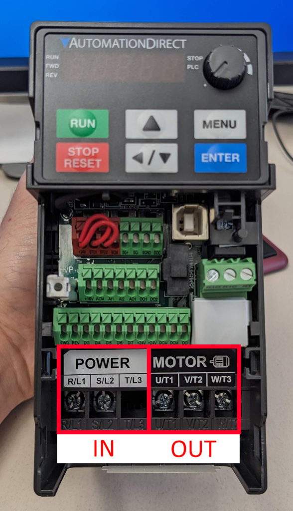
- VFD (in)
- VFD (out)
- Terminal Block in # (Example 46)
- Terminal Block out # (Example 46) (the number will be the same as “in”)
- Motor
VFD in wires are the two or three wires on the left labeled “R/L1”, “S/L2”, “T/L3”
VFD Out wires are the three wires on the right side labeled “U/T1”, “V/T2”, “W/T3”
From there power goes to terminal blocks that are either on the middle left or middle right side of the panel (the image below is of the right side).
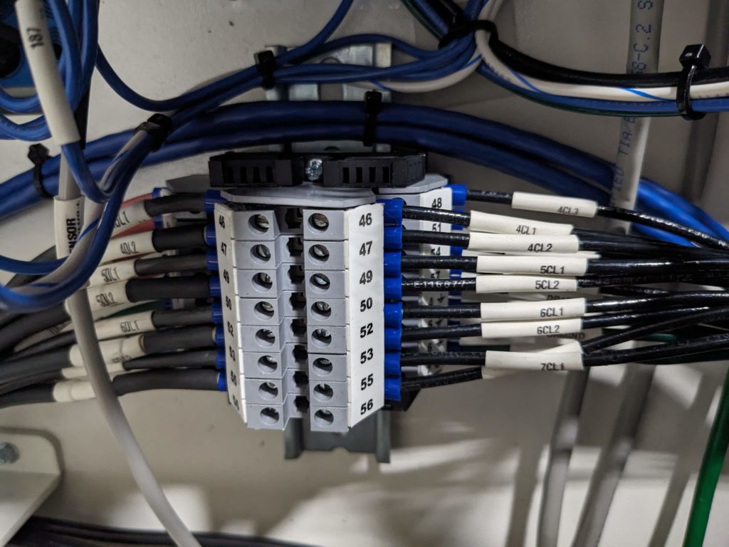
The power/GND wires from the VFD come in on the right side of the terminal block (in this example) pass through, then go out to the motors on the left side.
From the terminal block, the wires go directly to the motor
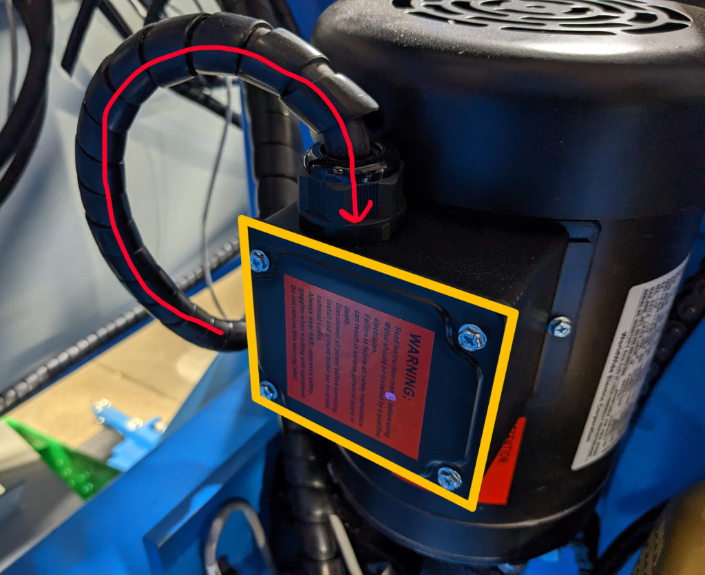
To access the motor wires, remove the four screws holding the cover in place.
Table of Contents