
Search for answers or browse our knowledge base.
Replacing a Blade Motor
Before You Begin
Safety: Stop the machine, follow the site lockout/tagout procedure, verify that hazardous energy is controlled, and release or secure stored mechanical and pneumatic energy before opening a panel, removing a guard, or adjusting components. Electrical work must be performed by a qualified technician.
To replace a blade motor there are 9 steps
- Power down the entire saw
- Remove the saw blade
- Unwire the (2) airlines and unwire the power cables
- Remove the brake assembly
- Using a hoist or forklift as a hoist remove the old blade motor
- Attach the new blade motor
- Re-attach the brake assembly
- Re-wire the power cables and replace the (2) airlines
- Attach the saw blade
Step 1: Power Down the Saw by Disengaging the Main Breaker
Turn off the power to the saw by throwing the main breaker switch on the stationary side

Step 2: Remove the Saw Blade
For this step, you will need a Torq wrench or ratchet and a T40 TORX bit. Simply remove the 3 (blade #5 has qty 6) screws attaching the blade to the motor.
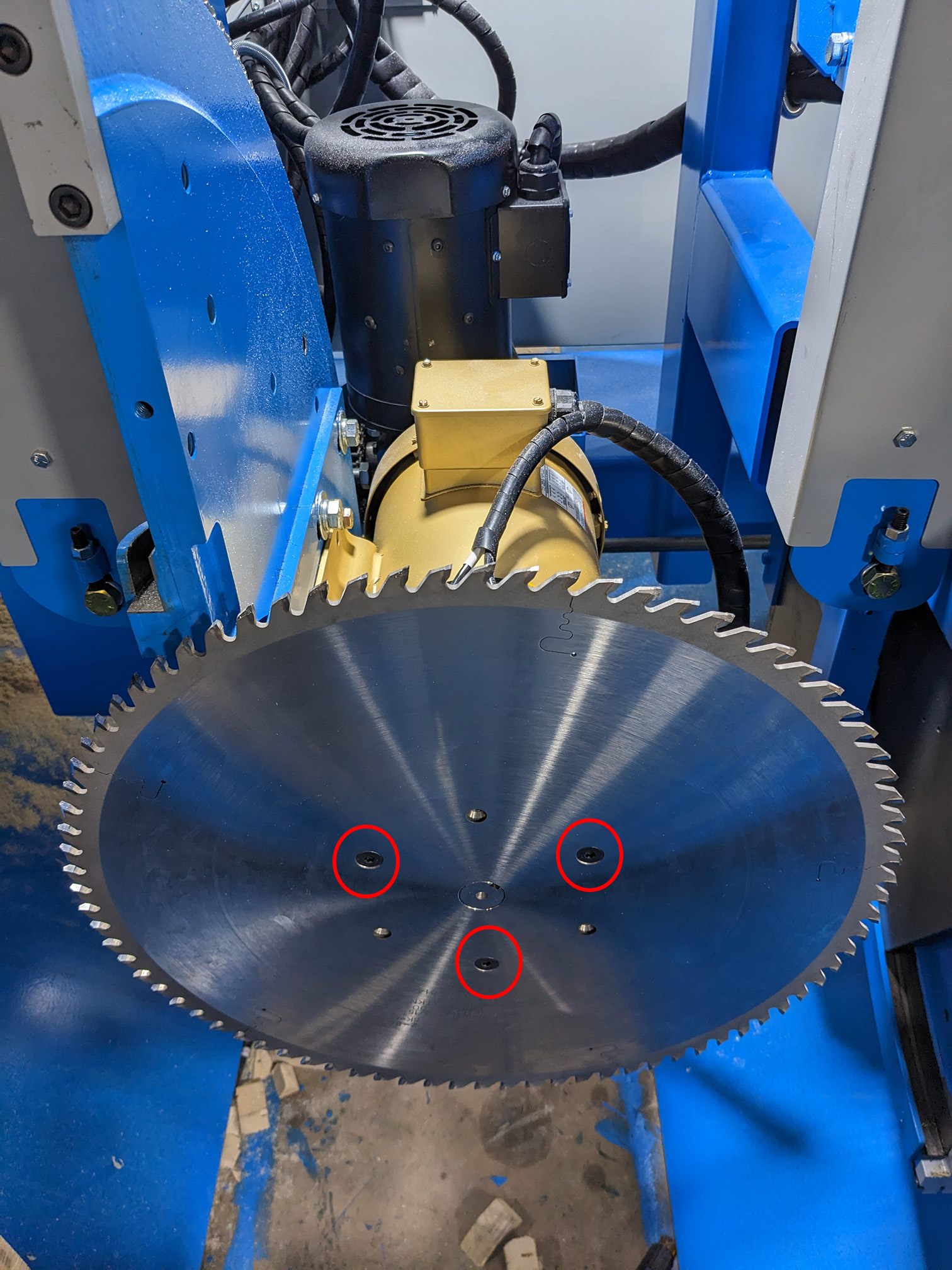
Step 3: Unwire both airlines and disconnect/unwire the power cables
For this step, I recommend that you write down/take note of which airline goes to the left/right connectors.
- Remove the two air hoses.
- Remove the four screws on the top of the electrical box on the motor.
- Disconnect the wires inside, and pull the electrical cord free from the motor.
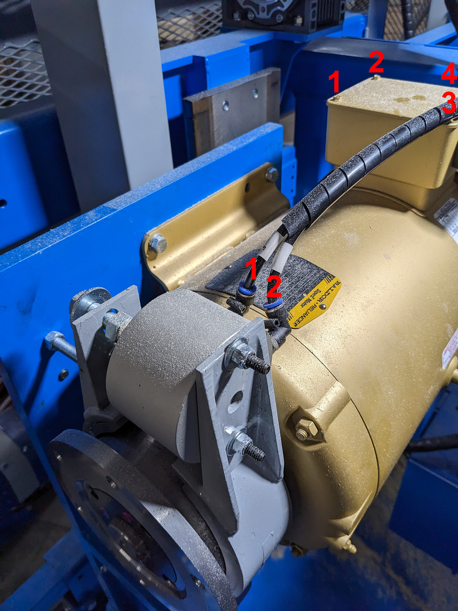
Step 4: Remove the Brake Assembly
To remove the assembly, start by removing bolts 1 & 2
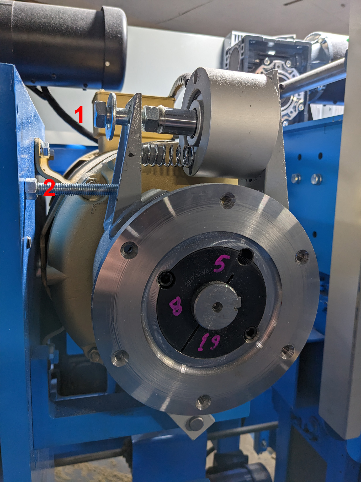
Then underneath the brake, you will find 2 set screws, use Allen wrenches to loosen those.
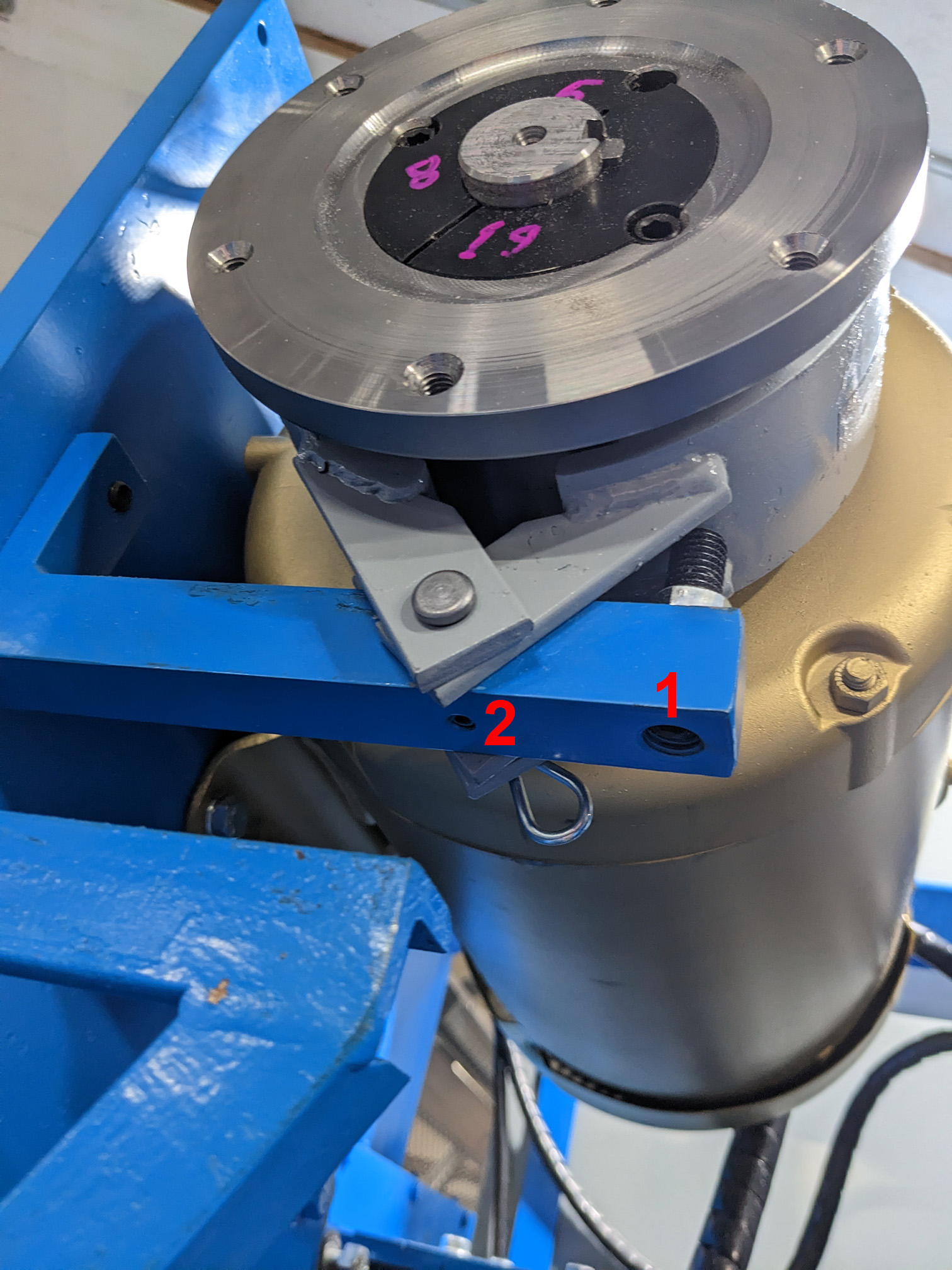
Once set screw #2 is loose you will be able to pull the pin out and the entire assembly should be able to be removed.
Step 5: Remove the Motor
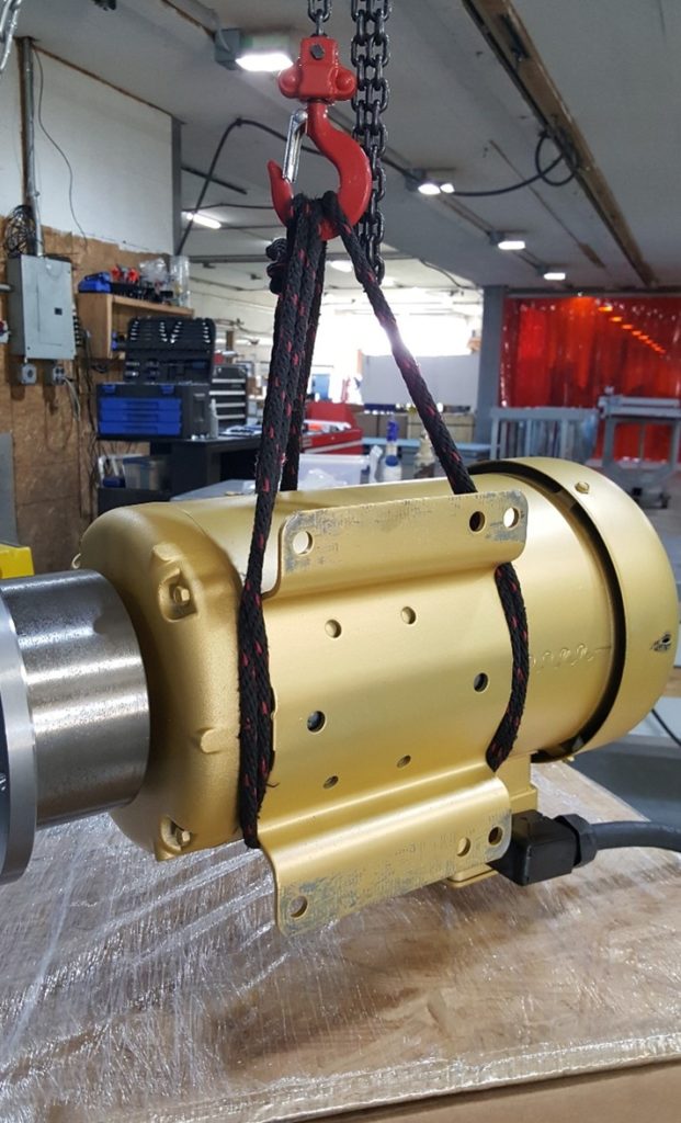
You are now ready to remove the motor, to remove we highly recommend that you use a winch or hoist of some sort to help lift the motors since they are heavy (motors 1–4 weigh 100 lb, and motor 5 weighs 150 lb). Wrap your rope around the motor the way pictured below or loop the rope around both ends (either way works). Remove the 4 bolts and you are half done with the motor swap.
Step 6: Replace the Motor
Using the winch, lift the new motor into place and bolt it back into place.
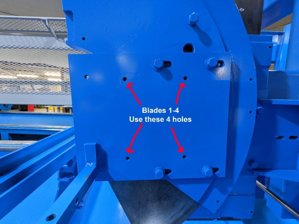
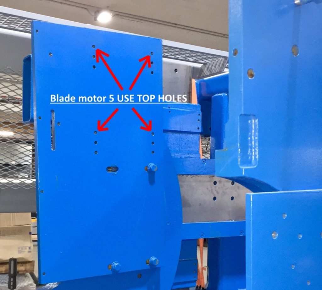
Step 7: Re-attach the Brake Assembly
Reverse the process that you went through in Step 4
Step 8: Reattach the Air Hoses and Reconnect the Electrical Box
Hopefully, you wrote down which cable goes to which of the two connectors. If you never wrote it down and don’t remember you can guess and then use the lock/unlock “Blade Brakes” button in the software to toggle their state and see if you guessed right or not.
If you have any questions about which wires to connect in the electrical box, we use the “Low Voltage” wiring scheme that is printed on a sticker on the side of the motor.
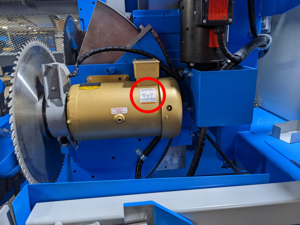
Connect wires (9 & 3), (8 & 2), (7 & 1), and (6, 5 & 4) together in their four groups using the four wire nuts.
Step 9: Re-attach the blade
Use the T40 TORX bit and a Torque wrench to torque the screws holding the blade to 20 ft-lbs.
Step 10: Power the Saw back on
Confirm the Result
After checking all connections and reinstalling covers, restore power through the approved startup procedure. Confirm that the correct device comes online without a disconnected-drive or communication warning, then test its command, direction, and stopping response in a controlled mode.
If the issue remains, record the exact on-screen message, affected component, indicator-light state, and the last change made. Provide those details to Enventek Technical Support; do not repeatedly recalibrate or replace parts without identifying the cause.