Search for answers or browse our knowledge base.
24V Power System
The Retro C has two 24V Power Systems, one on each end of the saw, stationary and carriage side. The 24-volt power supply has a safety against short circuits. If all of the VC1’s go offline on one end of the saw, potential options for the failure are a short in the 24-volt system.
The power supply has a green light that should stay solid if it it is functioning properly. If the light is turning pulsing then the power supply is turning on and off. This could be a failure of the power supply or it could be short in the system. An easy way to check is to remove a wire from the positive side of the 24v power supply. If the light turns solid green then there is most likely a short in the 24V system beyond the power supply.
In order to work on this problem we need to remove the power from groups of 24V power in order to narrow down the short circuit.
The 24V power supply gets power coming from wire 11 and 12, (on the stationary side) up from the bottom of the unit. The unit should read 27.4 volts.
NOTE: The power supply and DC-UPS need to be configured to both read 27.4 volts. Turn the dial on the power supply all the way left, and turn up the dial on the DC-UPS to exact as possible.
Then it travels through and creates power on the negative (-) and positive (+) at the top. It then passes through DC OK with a jumper, then exits 181 to CR29. The CR29 tells the DC-UPS, it has power, so CR29 should be on any time the power supply is on.
The power from positive (+) then travels wire 177 and enters DC-IN negative (-) and positive (+) on the DC-UPS unit on the bottom left side.
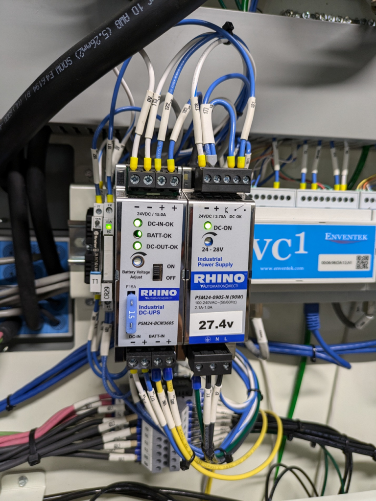
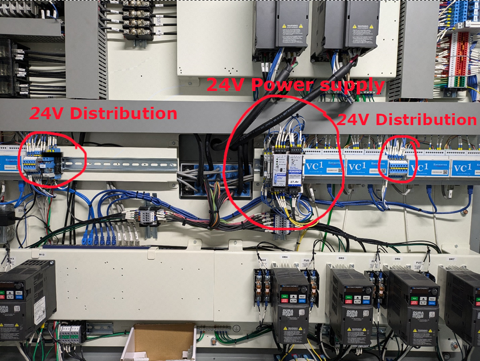
The 24V power then goes to the terminal blocks through wire 122, which leaves the DC-UPS and then goes to the right-side blue terminals to provide the power to the VC1’s. Then the Right-side blue terminals have a jumper wire that goes to the left side blue terminals. The blocks are joined by jumpers between the terminals, on most systems they are yellow or orange jumpers.
Disconnecting the jumper wire between these terminals eliminates everything on the left side that could be the short circuit. If that did not work, then start removing individual 24V connection going to each VC1 from the right terminal until the short is found.
Once the short circuit is found the component needs to be replaced.