
Search for answers or browse our knowledge base.
Temporary 24 V UPS Bypass: Qualified-Technician Procedure
This procedure temporarily removes the Rhino PSM24-BCM360S battery-control module from the 24 V VC1 power path. Use it only under Enventek Support direction when a failed UPS module prevents the VC1 controls from receiving stable power.
Consequences and safety: The bypass removes battery-backed control power, so the VC1s will shut down immediately during a power loss. This work must be completed by a qualified electrical technician using lockout/tagout, the machine schematic, a calibrated meter, and the terminal markings on the installed devices.
Before moving conductors
- Identify the exact stationary- or carriage-side panel being serviced.
- Photograph and label every conductor at the Rhino PSM24-0905-N power supply and PSM24-BCM360S module.
- Verify the wire numbers on the conductors themselves; do not rely on wire color alone.
- Lock out the machine and verify the absence of hazardous voltage.
- Confirm the required DC polarity from the machine schematic and the +/− markings on the devices. The panel photo below is a location reference, not a substitute for the schematic.
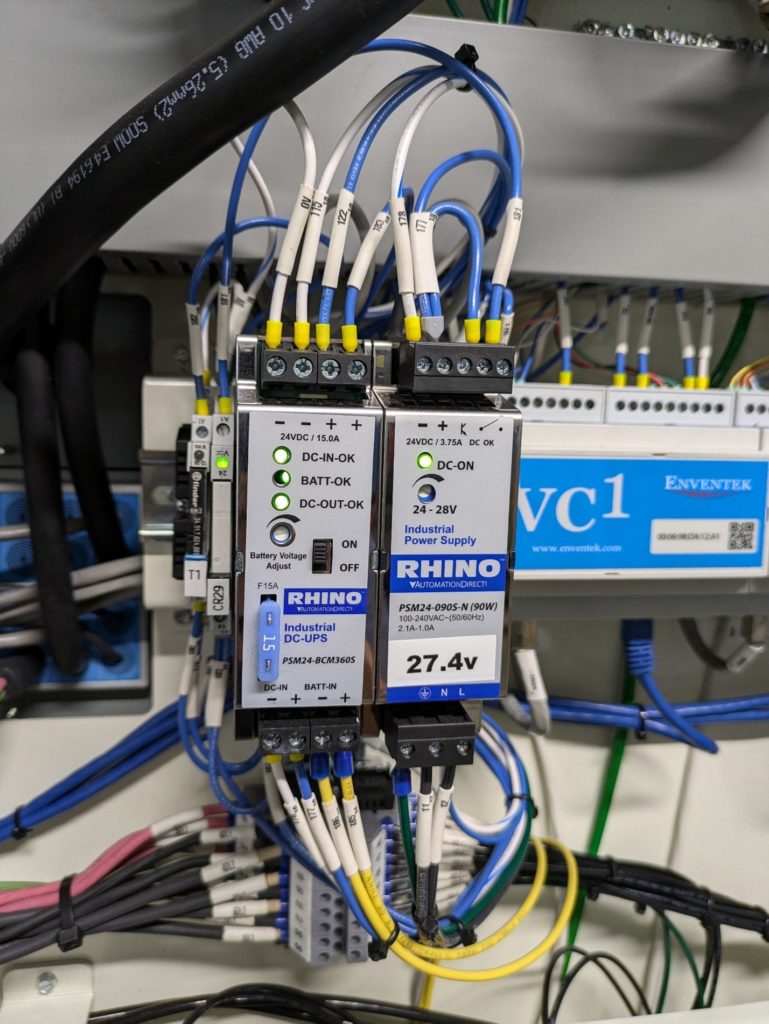
Documented conductor moves
- Remove wire 177 (blue) from its output terminal connection at the top of the Rhino PSM24-0905-N.
- Remove wire 178 (white with blue) from its output terminal connection at the top of the PSM24-0905-N.
- Remove wire 122 from the top of the PSM24-BCM360S and connect it to the verified power-supply output terminal vacated by wire 177.
- Remove wire 115 from the top of the PSM24-BCM360S and connect it to the verified power-supply output terminal vacated by wire 178.
Polarity verification is mandatory: An earlier version of this article contained conflicting positive/negative terminal descriptions. Use the device markings and machine schematic to verify the destination of wires 122 and 115 before energizing. Stop and contact Enventek Support if either identification is unclear.
Inspection before power-up
- No loose conductor strands are exposed.
- Every moved conductor is fully seated and secured to the manufacturer’s torque requirement.
- The removed UPS conductors are individually insulated and secured so they cannot contact a terminal or enclosure.
- All tools are removed and the enclosure is ready to be closed.
Energize and verify
- Restore power using the facility’s procedure.
- Have the qualified technician verify correct DC polarity and a stable control voltage. The Retro C 24 V system is configured for approximately 27.4 V DC.
- Confirm that the associated VC1s reconnect and retain stable communication.
- Test the affected controls at a controlled speed and confirm that the supply does not pulse, trip, or overheat.
- Label the panel clearly to show that the UPS is bypassed and arrange repair or replacement of the failed UPS component.
Do not treat this as a permanent repair. Reinstalling the UPS must also be completed with power locked out, using the schematic and Enventek Support guidance.