
Search for answers or browse our knowledge base.
-
Retro C
-
-
- Articles coming soon
-
- Replace the Retro C Computer
- Configure the Touchscreen Computer to Power On Automatically
- Replace the microSD Card in a Display Computer
- Transfer Files to the Retro C
- Replace the USB Drive in the Touchscreen Computer
- Configure a Newer Computer to Power On After an Outage
- Configure an Older Computer to Power On After an Outage
- Touchscreen Pointer Is Flipped or Mirrored
- Replace the Retro C Touchscreen USB Drive
- Retro C Touchscreen Is Black or Will Not Start
-
-
-
- Recover and Recalibrate a Stuck Angle or Centerline
- Replacing an Angle Encoder
- Angle Movement Overruns the Commanded Position
- Angle (Arch) Movement Overview
- Angle Chains – Proper Chain Tension
- Diagnose Unknown Blade Motor Noises
- Pivot Point Calibration Check
- Troubleshoot Power or Wiring for Angle Motors and VFDs
- Dirty Saw Head Slide: Symptoms and Cleaning
-
- Recover and Recalibrate a Stuck Angle or Centerline
- Calibrate Retro C Centerlines 1–5
- Advanced Centerline Recovery When Calibration Is Far Out
- Centerline (Vertical) Movement Overview
- Replace a Centerline Encoder
- Replacing a Centerline Gearbox
- Check the Centerline Maximum and Minimum Height Settings
- Tighten the Centerline Slides
- Adjust Centerline Chain Tension
-
-
- Third Scrap Drive Wiring and GS23 Programming
- Adjust or Tighten the Scrap Conveyor Belt
- Configure the Scrap or Incline Conveyor to Always Run
- Replacing the Scrap Motor
- Scrap Belt: Support Roller Replacement
- Scrap Belt Sweeper Adjustment and Inspection
- Scrap Belt Tracking and Alignment
- Retro C Scrap System Overview and Daily Checks
-
-
- VFD General Reference and Troubleshooting
- Drive (VFD) Disconnected Warning: Diagnosis and Recovery
- GS1 and GS2 VFD Reference
- GS20 VFD Reference
- GS20 ACM/DCM Common Wiring
- GS20 Standard VFD Wiring Reference
- GS3 VFD Reference
- Program a Replacement CFW Drive
- GS VFD Overvoltage Warning: Diagnosis and Safe Response
- VFD Replacement Options
- Yaskawa V1000 Blade Programming
- Program an AutomationDirect GS23 VFD
- Common VFD Wiring to VC1s
-
- Replace and Commission a VC1
- Replace a VC1: Mechanical and Electrical Procedure
- Add a Delay Diode Jumper to a VC1
- Configure the Software After Replacing a VC1
- Temporary 24 V UPS Bypass: Qualified-Technician Procedure
- VC1 Standard Jumper Removal
- 24 AWG-to-22 AWG VC1/VFD Cable Upgrade Wiring Reference
- VC1 Status Lights and Startup Diagnosis
-
- Encoder Wiring Diagram
- Stationary and Carriage Panel Cable Entry Layout
- Troubleshoot Power or Wiring for Angle Motors and VFDs
- Replace the Wires and Hoses in the Energy Chain
- Temporary 24 V UPS Bypass: Qualified-Technician Procedure
- 24 AWG-to-22 AWG VC1/VFD Cable Upgrade Wiring Reference
- Common VFD Wiring to VC1s
- Retro C Encoder Counts Move in the Wrong Direction
-
-
- Common Retro C Issues and Solutions
- Countdown Timer Warning with All VC1s and VFDs Disconnected
- Scrap Belt or Scrap Incline VFD Disconnected: Troubleshooting
- Recover and Recalibrate a Stuck Angle or Centerline
- Touchscreen Pointer Is Flipped or Mirrored
- Encoder Unplugged Error: Diagnosis and Recovery
- Stationary or Carriage Horizontals Will Not Move
- Error Messages and Warnings: Quick Index
- Retro C Will Not Start or Enable After Power-Up
- Retro C Calibration Will Not Hold or Changes After Restart
- Recover Retro C After an Unexpected Power Loss
-
-
-
Linear Pickline
-
- Foot Pedal Controls and Troubleshooting
- Unexpected Conveyor Movement Caused by a Foot Pedal Contact
- Front Conveyor Sensor: Location and Diagnosis
- Kindle Fire 8 Configuration
- Linear PickLine – Conveyor Sensor Integration
- Linear PickLine – Installation Requirements
- Linear PickLine – Installing the Brain Box
- SmartConveyor Air Stop: Operation and Troubleshooting
-
-
Plant One Projection
-
SmartConveyor
-
- Cable Pull Emergency-Stop System
- SmartConveyor V40 Encoder: Route, Replacement, and Verification
- Foot Pedal Controls and Troubleshooting
- Unexpected Conveyor Movement Caused by a Foot Pedal Contact
- Front Conveyor Sensor: Location and Diagnosis
- SmartConveyor Dual-Pedal Controls
- SmartConveyor Air Stop: Operation and Troubleshooting
-
-
Sticker Printer
-
NexPlate
Advanced Centerline Recovery When Calibration Is Far Out
Use this advanced procedure only when a centerline is so far outside its saved range that the normal centerline-calibration workflow cannot be completed. Common causes include a power loss during movement, a lumber collision, an incorrect calibration entry, or position drift on an older screw-drive centerline.
Advanced support procedure: The Manual Controls screen can command full motor power and this procedure deliberately approaches a mechanical end stop. Keep the saw area clear and perform it only under Enventek Support direction. Stop the command as soon as the end stop is reached; do not hold the motor stalled.
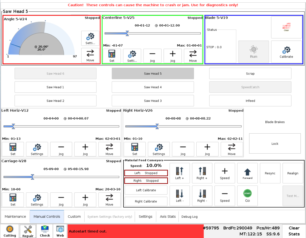
Select the affected centerline
- Open Repair → Manual Controls.
- Select the saw head and the centerline that requires recovery.
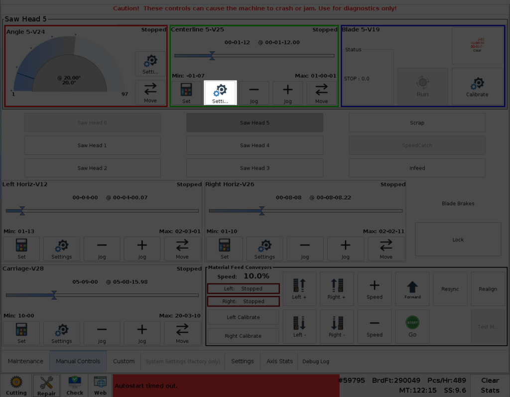
- Open Settings for that centerline. The screenshots use Centerline 5 as an example; select the actual affected centerline on your machine.
Establish the maximum reference
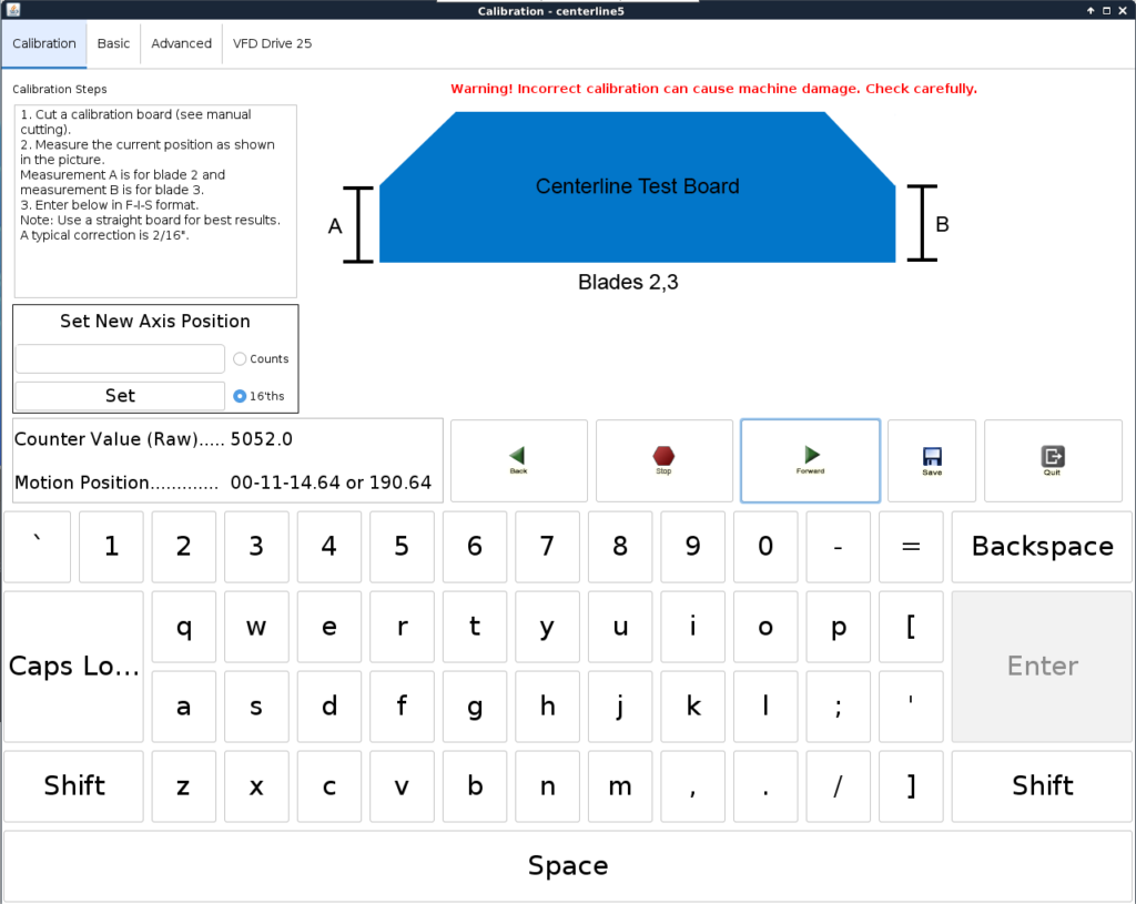
- Use the Forward control to move the centerline carefully toward its upper mechanical stop.
- Release the command immediately when the centerline reaches the stop and cannot move farther.
- Record the displayed Motion Position. The example shown is 190.64; your value may differ.
Correct the saved maximum position
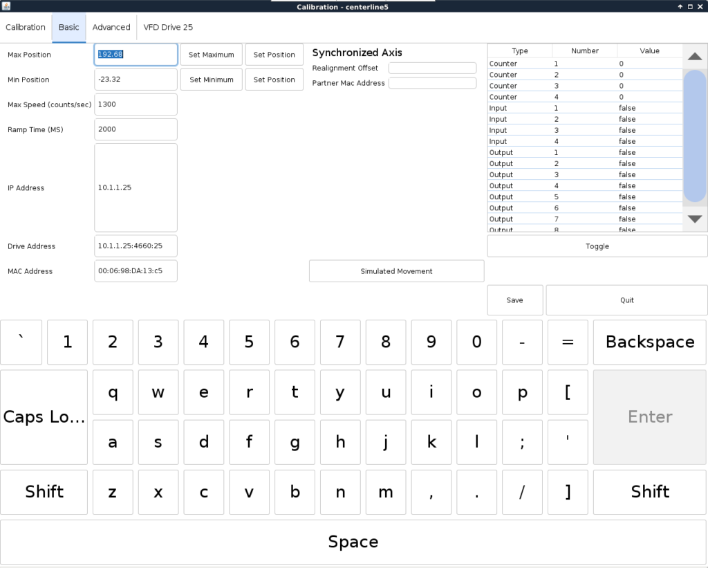
- Open the Basic tab.
- Compare the Motion Position you recorded with the Max Position field.
- If the values do not match, use only the Set Position control associated with Max Position. Do not press the other Set Position control.
Move away from the hard stop
Return to the Calibration tab and use Back to move the centerline down from the mechanical stop. A short movement is sufficient. This step prevents the motor from beginning the next setup already stalled at the stop. The controls on this screen may use 100% motor power instead of the approximately 90% used by the normal cutting window.
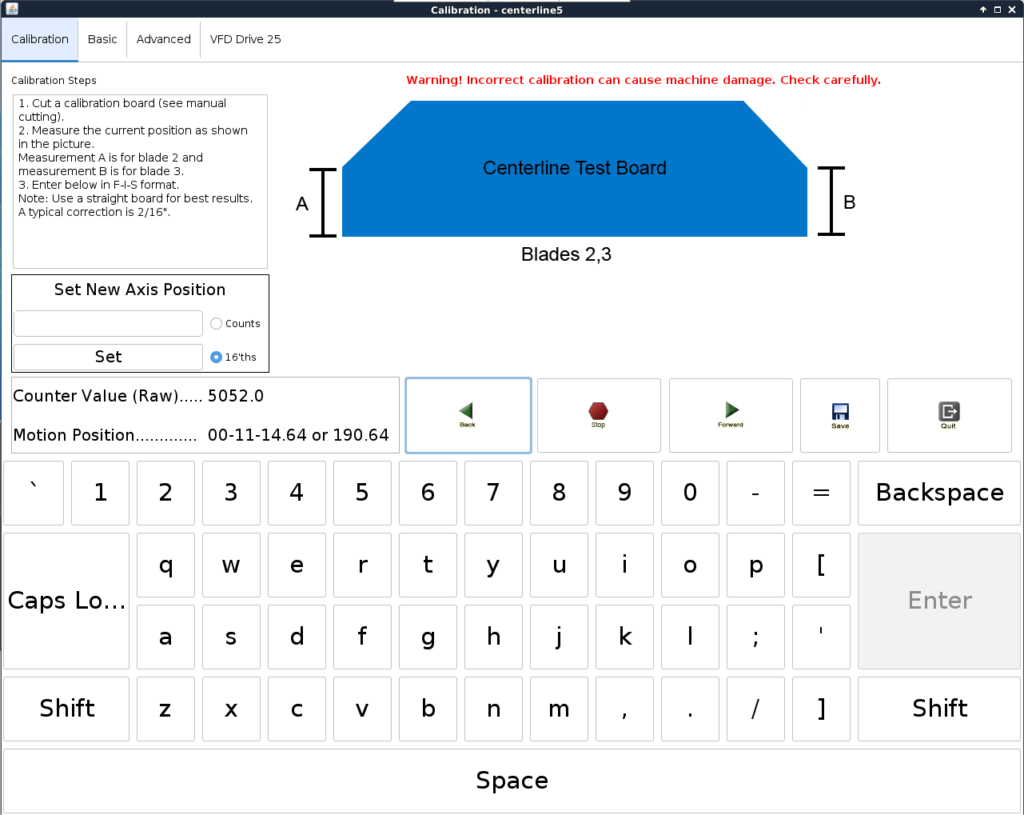
Complete standard calibration
- Exit the advanced settings after confirming that the centerline is within its maximum bounds.
- Continue with Calibrate Retro C Centerlines 1–5.
- Cut and measure a test board using the standard procedure.
- Repeat the test and confirm that the measurement and return position are consistent.
If the centerline cannot reach the stop smoothly, the displayed position jumps, or the motor stalls before the mechanism reaches its limit, stop and investigate the drive, chain or screw mechanism, encoder, and wiring before changing calibration.