Search for answers or browse our knowledge base.
-
Retro C
-
-
- Articles coming soon
-
- How to Replace the Retro C's Computer
- Configuring the Touchscreen Computer's "Power-On"
- How to replace micro USB on the display computers
- How To: Transfer Files to the Retro C
- How to replace the USB hard drive on the touch screen computer
- New computer set bios power on
- Old computer set bios to power on
- TouchScreen Flip / Mirror Issue
-
-
-
- Stuck Angle or Centerline - How to Recover & Recalibrate
- Replacing an Angle Encoder
- Angle movements over run when going to position.
- Angle (Arch) Movements - Overview
- Angle Chains - Proper Chain Tension
- Diagnosing Unknown Noises Coming from Blade Motor
- Pivot Point Check
- Power or Wiring Troubleshooting for Angle Motors or VFDs
- Dirty Slide
-
- Stuck Angle or Centerline - How to Recover & Recalibrate
- How To: Calibrate Centerline 1-5
- How To: Calibrate Centerline 1-5 (Advanced)
- Centerline (Vertical) Movements - Overview
- Replacing a Centerline Encoder
- Replacing a Centerline Gearbox
- Checking the Centerline Maximum & Minimum (Max & Min) Height Setting
- How to Tighten the Centerline Slides
- How To: Tension The Centerline Chains
-
-
-
- Common Retro C issues and solutions
- Countdown Timer / E-Stop Troubleshooting
- Scrap Belt or Scrap Incline VFD Disconnected: Troubleshooting
- Stuck Angle or Centerline - How to Recover & Recalibrate
- TouchScreen Flip / Mirror Issue
- Troubleshooting: Encoder Unplugged Error
- Troubleshooting: The Stationary or Carriage Side Horizontals Won't Move Anymore
-
-
Linear Pickline
-
Plant One Projection
-
SmartConveyor
-
Sticker Printer
Retro C: How To Add a Delay Diode Jumper to VC1
Adding a delay diode jumper to the VC1
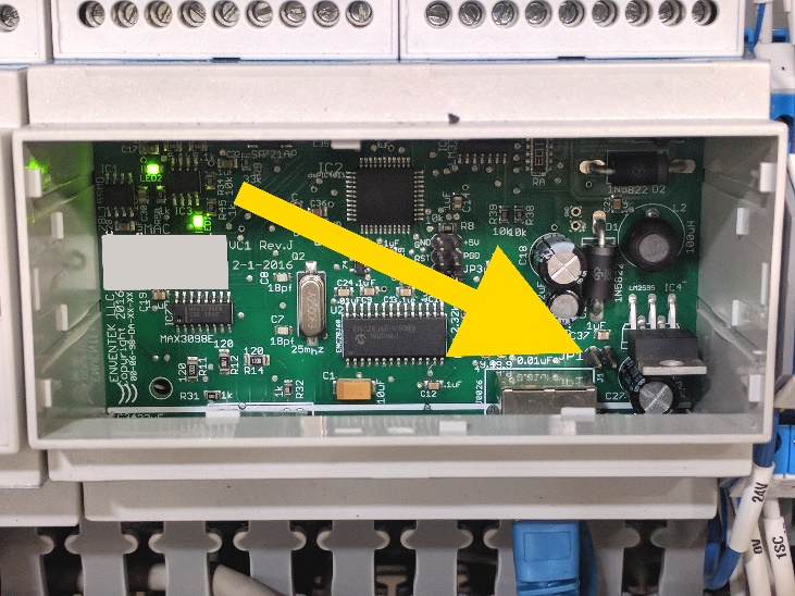
Step 1a: Locate the row of VC1’s in the electrical panel at each end of the saw. Each VC1 has a label starting with the letter ‘V’ followed by a number. To gain access to the circuit board inside the plastic enclosure, use a small screwdriver or the tip of a sharp object to pry open the plastic cover. Push the tip of the screwdriver into one of the four small slots around the edge of the blue sticker on the front of the VC1 and gently pry it open.
Step 1b: We will need to open each VC1 so start by opening the cover on the one furthest to your left. Once opened, try to locate the two solitary jumper pins at the bottom right of the VC1 (see picture above with yellow arrow). If your VC1 does not have a pair of jumper pins or your VC1 has a pair of pins but they are already shorted by a shunt jumper, close the VC1 cover and move to the next VC1. If you find the pair of jumper pins and they have no jumper connected to the pins, then move to Step 1c below to add a delay diode jumper.
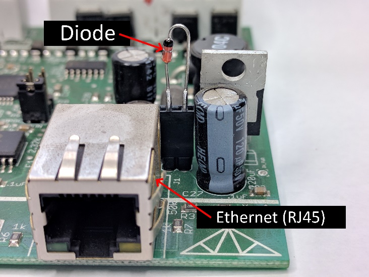
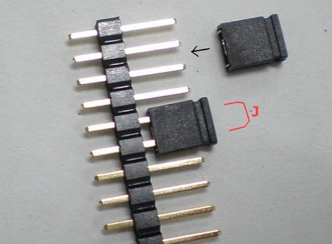
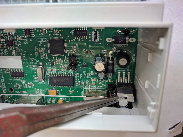
Step 1c: Using a pair of needle nose pliers, tweezers or possibly your fingers, insert the diode modified jumper provided in your upgrade kit on to the jumper pins. NOTE−The orientation of the jumper is critical to the proper operation of the VC1 AND do not clamp on to the glass diode with the pliers or tweezers, instead clamp on to the metal wire. Make sure the diode is facing towards your left, closest to the ethernet (RJ45) connector. See photo above.
Step 1d: Replace the VC1 cover and move to the next VC1 on the panel. Please make sure you open and check each VC1 in both the stationary and carriage panels.