Search for answers or browse our knowledge base.
VC1 Mechanical and Electrical replacement procedure
Overview
The replacement of a VC1 involves two main steps – Mechanical/Electrical and Software configuration. The Mechanical/Electrical steps entail removing and replacing wires and mounting the new VC1 into the machine. The subsequent step involves configuring the software to adapt the VC1 to your specific equipment.
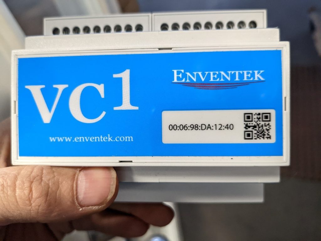
- Document MAC Addresses: Prior to proceeding, record the MAC addresses of both the VC1 you are removing and the new VC1 you are installing. You can use the provided sheet to write down the MAC addresses or take a photo of them for future reference.
- Disconnect Wires: Carefully unscrew and disconnect all wires connected to the faulty VC1 that needs replacement.
- Remove the Old VC1: Take out the faulty VC1 from its position in the machine.
- Install the New VC1: Place the new VC1 into the same spot where the old one was situated. Reconnect all the wires to the appropriate ports on the new VC1.
Detail Steps
Step 1) Obtain MAC Addresses: To proceed with the software configuration, it is crucial to have both the MAC addresses of the old and new VC1 units. The MAC address can be found on the top of the VC1 and is a string of 12 alphanumeric characters. Remember that the first eight digits are always the same, and you only need to note down the last four characters. For example, 12:40.
Following these steps carefully will ensure a successful replacement of the VC1, both mechanically and electronically, and configure it to function optimally with your equipment.
Step 2) Removing Wires and Documenting Wiring:
a) Pop the Terminal Covers: Carefully remove the covers from the terminals of the VC1 to gain access to the wires.
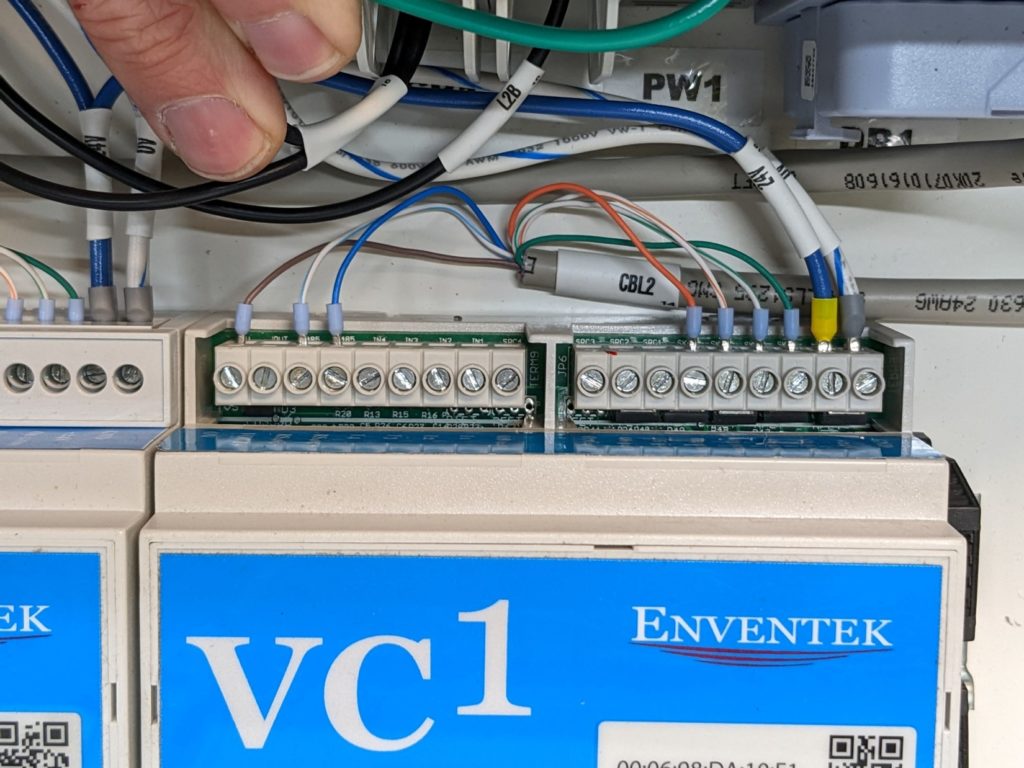
b) Capture Wiring Configuration: Before disconnecting any wires, take a clear picture of the current wiring arrangement. The image provided below is merely an example and may not correspond to your VC1’s actual wiring configuration. It is essential to replicate the existing wiring when connecting the new VC1. Pay close attention to both the wire colors and the specific harnesses from which the wires originate.
c) Note Wire Matches: Take note of wire matches to ensure correct reconnection. In cases where wires of the same color are found in different cable harnesses, be diligent in matching and connecting them correctly. For instance, if you encounter a Brown wire from CBL2 in the photo provided, it should be connected to the 0V port of the new VC1.
By carefully following these steps and documenting the wiring arrangement, you will be able to successfully replace the VC1 while maintaining the correct electrical connections.
Step 3) Removing RJ45 (Ethernet Plugs):
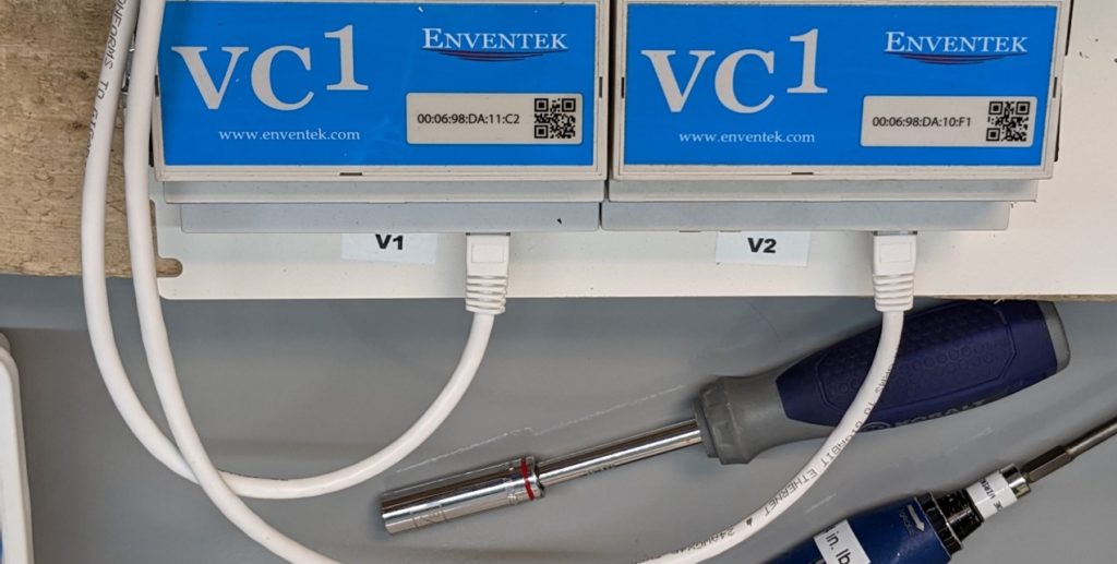
a) Locate RJ45 Ethernet Plugs: Identify the RJ45 Ethernet plugs on the bottom of the VC1 module.
b) Note Port Connections: Before removing the plugs, take note of which plug is connected to each specific port on the VC1. This step is crucial for proper reinstallation.
c) Carefully Disconnect Plugs: Gently remove the RJ45 Ethernet plugs from their respective ports on the VC1, ensuring not to damage the connectors or ports during the process.
By following these steps, you will successfully detach the RJ45 Ethernet plugs from the VC1 while keeping track of their correct positions for later reconnection.
Step 4) Removing the VC1:
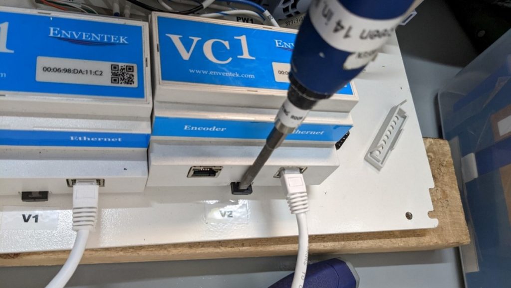
a) Locate the Black Latch: Identify the black latch positioned under the Ethernet ports of the VC1 module.
b) Use a Regular Screwdriver: Take a regular screwdriver and carefully position the tip under the black latch.
c) Pry Down the Latch: Apply gentle pressure on the screwdriver to pry the black latch downwards. This action will release the VC1 from its mounting rail.
d) Lift/Rotate the VC1: With the latch disengaged, carefully lift or rotate the VC1 to remove it from the rail.
By following these steps, you can successfully detach the VC1 from its mounting rail using a regular screwdriver and without causing any damage to the module or the rail.
Step 5) Reinstall the New VC1:
Place the new VC1 back into the same location where the old VC1 was removed.
Step 6) Reconnect Wires and Pop Terminal Covers:
a) Pop the Terminal Covers: Open the terminal covers to expose the connection points.
b) Wire Placement: Carefully reconnect the wires to the same spots they were in when you started the replacement process. Refer to the picture you took earlier or the documentation you made to ensure the wiring matches the original configuration.
c) Wire Colors and Harnesses: Pay close attention to wire colors and the harnesses they are coming from. If there were multiple wires of the same color in different harnesses, ensure they are matched correctly.
d) Secure Terminal Covers: Once all the wires are correctly reconnected, snap the terminal covers back into place.
By following these steps, you will have successfully installed the new VC1 and ensured that the wires are reconnected precisely as they were before the replacement, thus maintaining the proper functionality of the equipment.
Congratulations the VC1 mechanical installation is complete.
Continue to the software steps in order to complete the software configuration.