
Search for answers or browse our knowledge base.
Countdown Timer Warning with All VC1s and VFDs Disconnected
Applicability
| Product | Retro C |
|---|---|
| Subsystem | Network switch and COMP_NET communication |
| Drive/controller | VC1 and VFD network |
| Skill level | Qualified electrical technician for enclosure or power tests |
| Lockout/tagout | Required for enclosure work; follow the facility procedure |
When This Article Applies
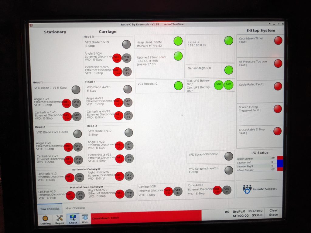
Use this procedure when the Retro C Countdown Timer warning will not clear and the Check screen shows that none of the stationary or carriage VC1s and VFDs are connected. When all of these devices disappear at the same time, the most likely cause is loss of power or communication at the main network switch—not simultaneous failure of every controller and drive.
If only one VFD is disconnected, use Drive (VFD) Disconnected Warning: Diagnosis and Recovery instead.
Safety
The main stationary enclosure contains hazardous voltage. Only qualified personnel should open the enclosure, test voltage, inspect CB9, or change wiring. Follow your facility’s E-STOP and lockout/tagout procedures. Do not touch exposed electrical components while troubleshooting indicator lights.
1. Confirm the Symptom
- Open the Check tab.
- Confirm that the stationary and carriage VC1s and VFDs all show disconnected.
- Record any other warnings before restarting or changing anything.
2. Check the Main Network Switch
A qualified person should inspect the network switch in the main, large stationary enclosure. A powered and active switch should show multiple green indicator lights.
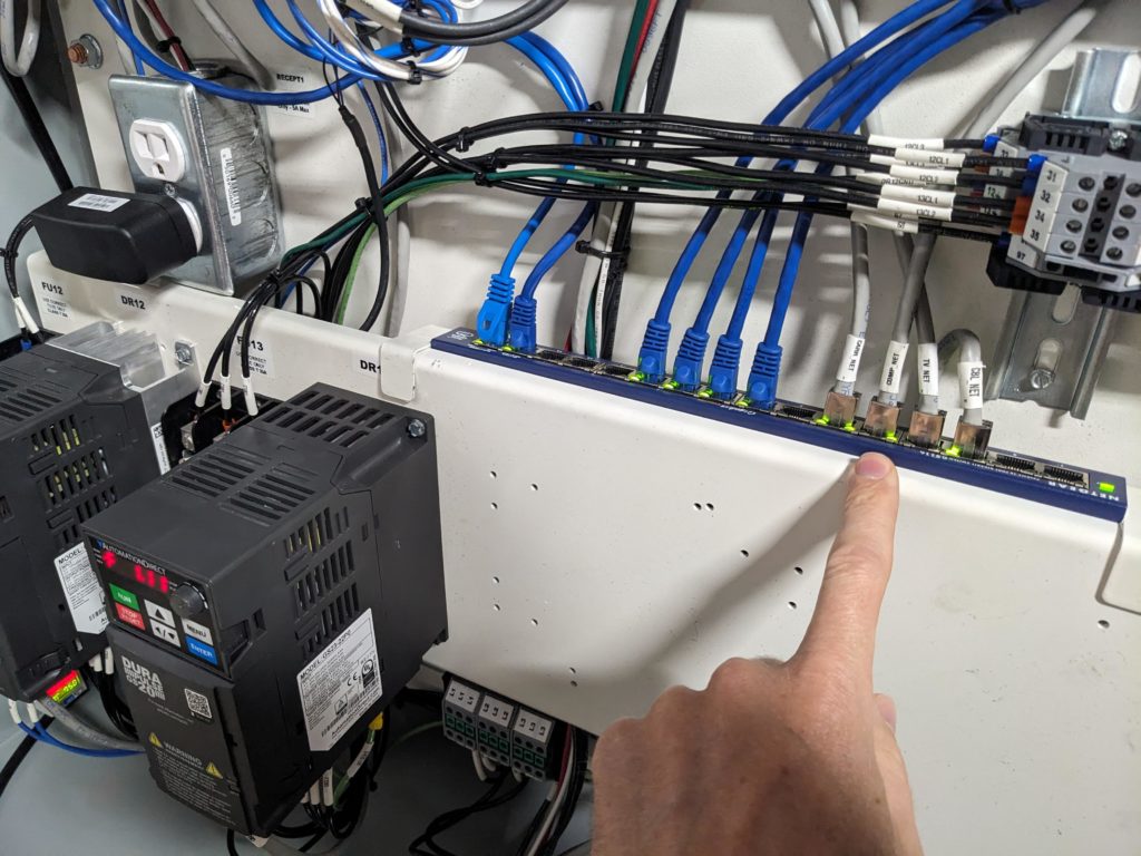
- No green lights: The network switch likely has no power. Continue to the power checks below.
- Green lights are present: Skip to the COMP_NET cable checks.
3. Check Network-Switch Power
- Verify that the network-switch power adapter is fully plugged into the 110 V receptacle to the left of the switch.
- Verify that the power plug at the back of the network switch is fully seated.
- If the adapter and switch connection are secure but the switch has no lights, have a qualified person inspect the outlet circuit and CB9.
4. Check Breaker CB9
CB9 supplies the network-switch outlet and is the breaker on the far left. On this installation, a tripped CB9 shows green.
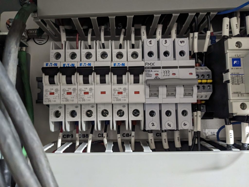
- Have a qualified person confirm whether CB9 is tripped.
- Inspect the circuit for an obvious problem before resetting the breaker according to the approved electrical procedure.
- Do not repeatedly reset CB9. If it trips again, leave it off and contact Enventek or a qualified electrician.
5. Check the COMP_NET Cable
If the network switch has power, check the cable labeled COMP_NET. This cable connects the touchscreen network switch to the switch in the stationary enclosure.
- Confirm that COMP_NET is fully inserted at both ends.
- The cable may be connected to any port on the switch.
- Check for a green link light at the port used by COMP_NET.
- If that port has no green link light, move the cable to another known-working port. Do not disturb other network connections unnecessarily.
6. Test with a Known-Good Cable
If both switches have power but the COMP_NET port does not show a link, a qualified technician can temporarily run a known-good network cable between the touchscreen-panel switch and the stationary-enclosure switch.
- If communication returns with the temporary cable, reterminate the existing cable ends or replace the COMP_NET cable.
- If communication does not return, restore the original connections and contact Enventek before replacing the switches or controllers.
What Correct Looks Like
- The main network switch has power and normal green link/activity lights.
- The COMP_NET port shows a green link light.
- The Check screen shows the stationary and carriage VC1s and VFDs connected again.
- The Countdown Timer warning clears after communication is restored.
Contact Enventek If
- CB9 trips again.
- The network switch remains unpowered with a working outlet and secure adapter.
- Both switches have power but no COMP_NET link can be established.
- The network link returns but the VC1s and VFDs remain disconnected.
Contact Enventek Technical Support at 269-815-4150 and report the Check-screen state, network-switch lights, CB9 state, and COMP_NET test results.