
How Can We Help?
Search for answers or browse our knowledge base.
-
Retro C
-
-
- Articles coming soon
-
- Replace the Retro C Computer
- Configure the Touchscreen Computer to Power On Automatically
- Replace the microSD Card in a Display Computer
- Transfer Files to the Retro C
- Replace the USB Drive in the Touchscreen Computer
- Configure a Newer Computer to Power On After an Outage
- Configure an Older Computer to Power On After an Outage
- Touchscreen Pointer Is Flipped or Mirrored
- Replace the Retro C Touchscreen USB Drive
- Retro C Touchscreen Is Black or Will Not Start
-
-
-
- Recover and Recalibrate a Stuck Angle or Centerline
- Replacing an Angle Encoder
- Angle Movement Overruns the Commanded Position
- Angle (Arch) Movement Overview
- Angle Chains – Proper Chain Tension
- Diagnose Unknown Blade Motor Noises
- Pivot Point Calibration Check
- Troubleshoot Power or Wiring for Angle Motors and VFDs
- Dirty Saw Head Slide: Symptoms and Cleaning
-
- Recover and Recalibrate a Stuck Angle or Centerline
- Calibrate Retro C Centerlines 1–5
- Advanced Centerline Recovery When Calibration Is Far Out
- Centerline (Vertical) Movement Overview
- Replace a Centerline Encoder
- Replacing a Centerline Gearbox
- Check the Centerline Maximum and Minimum Height Settings
- Tighten the Centerline Slides
- Adjust Centerline Chain Tension
-
-
- Third Scrap Drive Wiring and GS23 Programming
- Adjust or Tighten the Scrap Conveyor Belt
- Configure the Scrap or Incline Conveyor to Always Run
- Replacing the Scrap Motor
- Scrap Belt: Support Roller Replacement
- Scrap Belt Sweeper Adjustment and Inspection
- Scrap Belt Tracking and Alignment
- Retro C Scrap System Overview and Daily Checks
-
-
- VFD General Reference and Troubleshooting
- Drive (VFD) Disconnected Warning: Diagnosis and Recovery
- GS1 and GS2 VFD Reference
- GS20 VFD Reference
- GS20 ACM/DCM Common Wiring
- GS20 Standard VFD Wiring Reference
- GS3 VFD Reference
- Program a Replacement CFW Drive
- GS VFD Overvoltage Warning: Diagnosis and Safe Response
- VFD Replacement Options
- Yaskawa V1000 Blade Programming
- Program an AutomationDirect GS23 VFD
- Common VFD Wiring to VC1s
-
- Replace and Commission a VC1
- Replace a VC1: Mechanical and Electrical Procedure
- Add a Delay Diode Jumper to a VC1
- Configure the Software After Replacing a VC1
- Temporary 24 V UPS Bypass: Qualified-Technician Procedure
- VC1 Standard Jumper Removal
- 24 AWG-to-22 AWG VC1/VFD Cable Upgrade Wiring Reference
- VC1 Status Lights and Startup Diagnosis
-
- Encoder Wiring Diagram
- Stationary and Carriage Panel Cable Entry Layout
- Troubleshoot Power or Wiring for Angle Motors and VFDs
- Replace the Wires and Hoses in the Energy Chain
- Temporary 24 V UPS Bypass: Qualified-Technician Procedure
- 24 AWG-to-22 AWG VC1/VFD Cable Upgrade Wiring Reference
- Common VFD Wiring to VC1s
- Retro C Encoder Counts Move in the Wrong Direction
-
-
- Common Retro C Issues and Solutions
- Countdown Timer Warning with All VC1s and VFDs Disconnected
- Scrap Belt or Scrap Incline VFD Disconnected: Troubleshooting
- Recover and Recalibrate a Stuck Angle or Centerline
- Touchscreen Pointer Is Flipped or Mirrored
- Encoder Unplugged Error: Diagnosis and Recovery
- Stationary or Carriage Horizontals Will Not Move
- Error Messages and Warnings: Quick Index
- Retro C Will Not Start or Enable After Power-Up
- Retro C Calibration Will Not Hold or Changes After Restart
- Recover Retro C After an Unexpected Power Loss
-
-
-
Linear Pickline
-
- Foot Pedal Controls and Troubleshooting
- Unexpected Conveyor Movement Caused by a Foot Pedal Contact
- Front Conveyor Sensor: Location and Diagnosis
- Kindle Fire 8 Configuration
- Linear PickLine – Conveyor Sensor Integration
- Linear PickLine – Installation Requirements
- Linear PickLine – Installing the Brain Box
- SmartConveyor Air Stop: Operation and Troubleshooting
-
-
Plant One Projection
-
SmartConveyor
-
- Cable Pull Emergency-Stop System
- SmartConveyor V40 Encoder: Route, Replacement, and Verification
- Foot Pedal Controls and Troubleshooting
- Unexpected Conveyor Movement Caused by a Foot Pedal Contact
- Front Conveyor Sensor: Location and Diagnosis
- SmartConveyor Dual-Pedal Controls
- SmartConveyor Air Stop: Operation and Troubleshooting
-
-
Sticker Printer
-
NexPlate
< All Topics
Print
Replace the microSD Card in a Display Computer
Updated
PlantOne Projection systems and front or rear TV displays use a small Raspberry Pi computer that starts from a microSD card. Replace the card when Enventek Support supplies an updated or repaired display image.
Locate the display computer
The Raspberry Pi is normally zip-tied to the TV, mounted behind the display, or installed nearby.
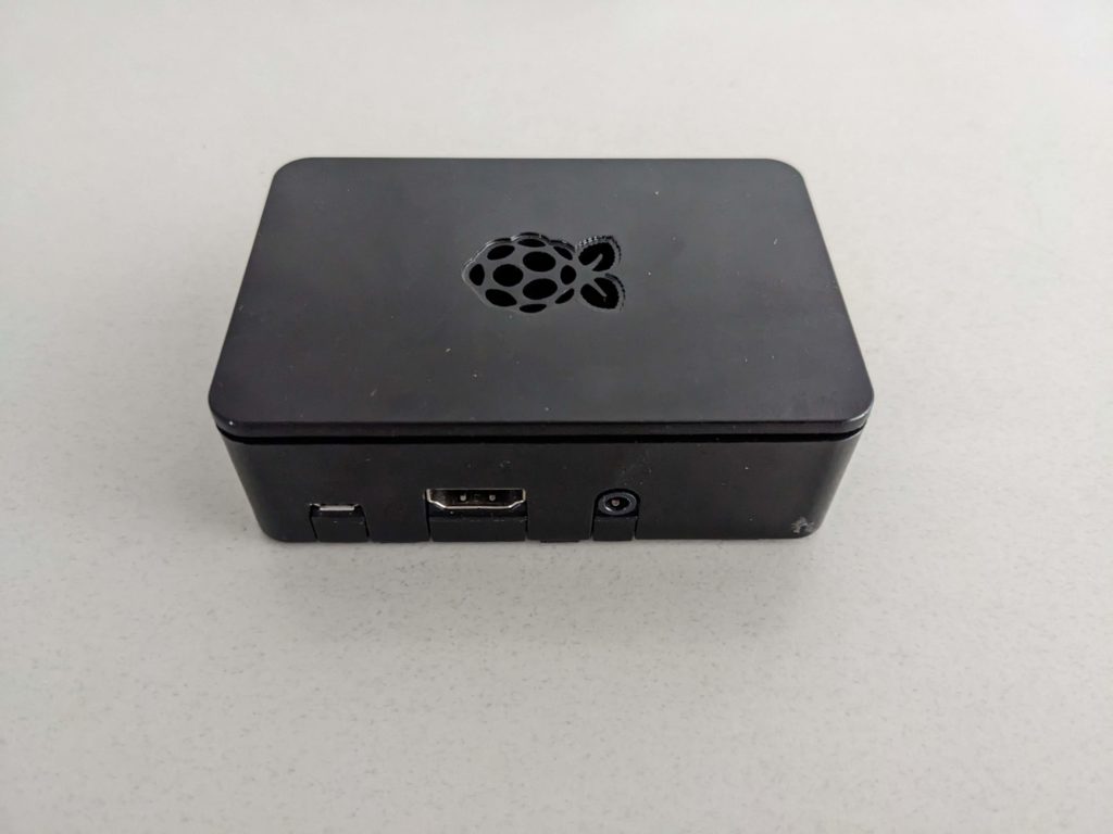
Protect the card: Remove power before touching the microSD card. Removing or inserting it while the Raspberry Pi is powered can corrupt the file system.
Remove the existing card
- If the display software provides a shutdown command, allow it to finish before removing power.
- Disconnect the Raspberry Pi power cable, normally a USB cable. Confirm that its LEDs are off.
- Locate the microSD slot. A spring-loaded card is pressed inward slightly and released; a friction-fit card pulls straight out.
- Note the card’s orientation and store the old card in a labeled, static-safe container.
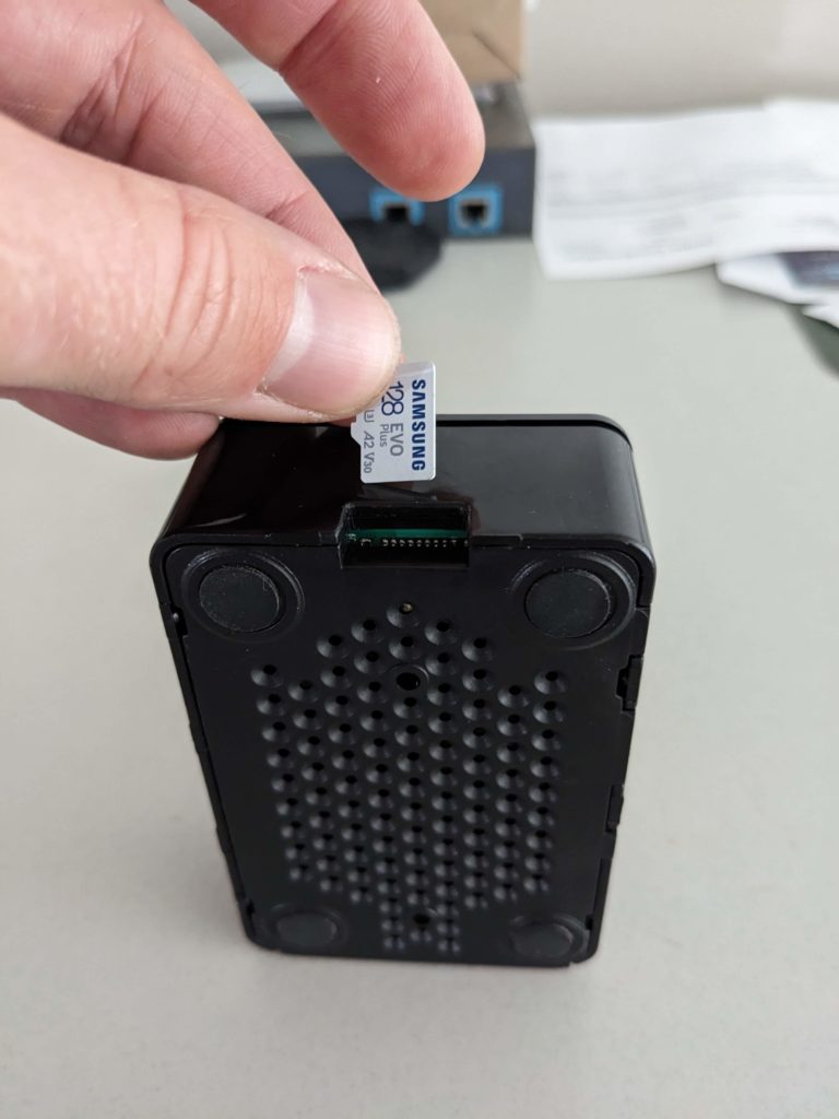
Install the replacement
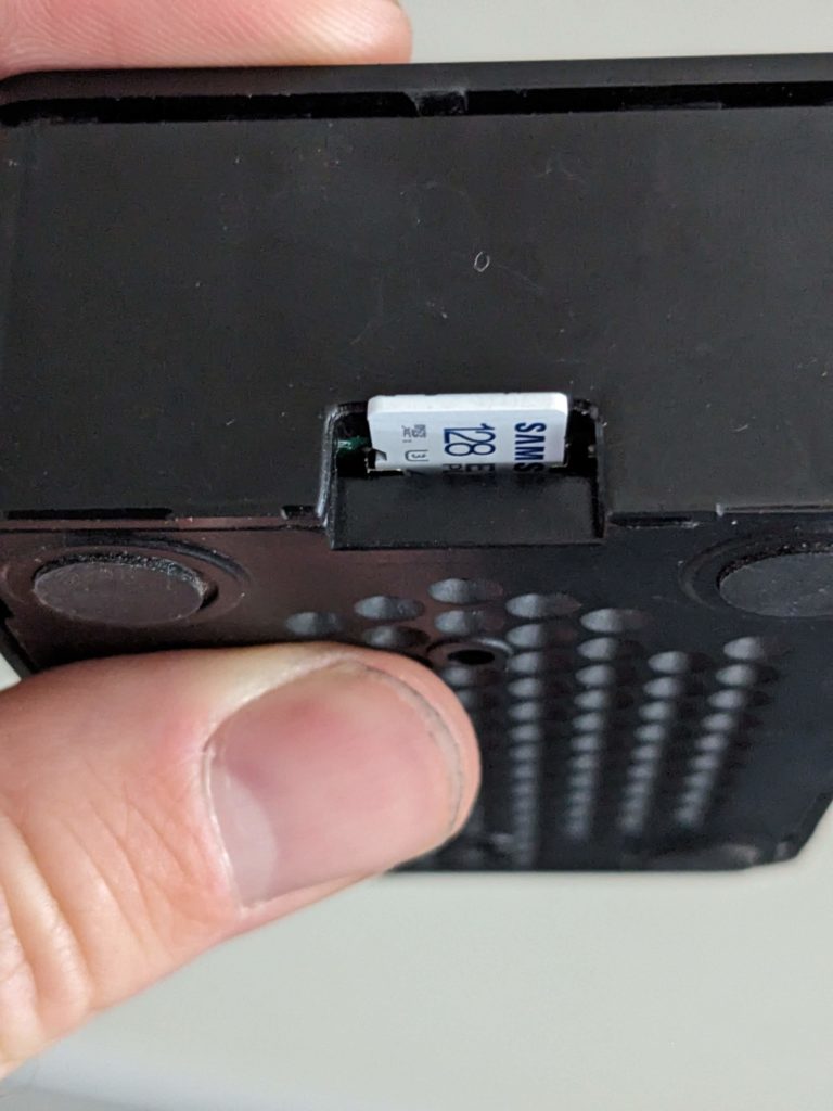
- Hold the replacement card by its edges and align it in the same orientation.
- Insert it without forcing it. A spring-loaded card should latch; a friction-fit card should sit fully and evenly.
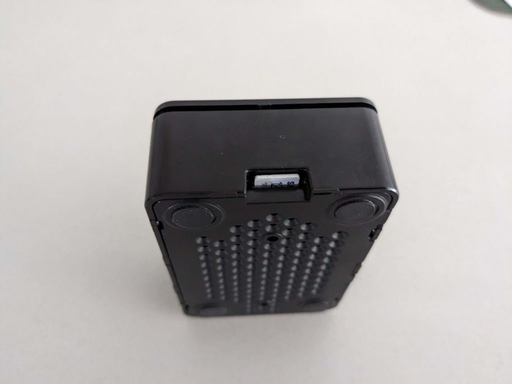
Power up and verify
- Reconnect power and allow the Raspberry Pi to complete its boot sequence.
- Confirm that the expected PlantOne or TV display appears.
- Verify that the display receives current production information and updates normally.
- Check the video and network connections before securing the computer.
- If the display does not boot, remove power before reseating the card and contact Enventek Support with any message or LED pattern.
Related Articles
Table of Contents