
Search for answers or browse our knowledge base.
-
Retro C
-
-
- Articles coming soon
-
- Replace the Retro C Computer
- Configure the Touchscreen Computer to Power On Automatically
- Replace the microSD Card in a Display Computer
- Transfer Files to the Retro C
- Replace the USB Drive in the Touchscreen Computer
- Configure a Newer Computer to Power On After an Outage
- Configure an Older Computer to Power On After an Outage
- Touchscreen Pointer Is Flipped or Mirrored
- Replace the Retro C Touchscreen USB Drive
- Retro C Touchscreen Is Black or Will Not Start
-
-
-
- Recover and Recalibrate a Stuck Angle or Centerline
- Replacing an Angle Encoder
- Angle Movement Overruns the Commanded Position
- Angle (Arch) Movement Overview
- Angle Chains – Proper Chain Tension
- Diagnose Unknown Blade Motor Noises
- Pivot Point Calibration Check
- Troubleshoot Power or Wiring for Angle Motors and VFDs
- Dirty Saw Head Slide: Symptoms and Cleaning
-
- Recover and Recalibrate a Stuck Angle or Centerline
- Calibrate Retro C Centerlines 1–5
- Advanced Centerline Recovery When Calibration Is Far Out
- Centerline (Vertical) Movement Overview
- Replace a Centerline Encoder
- Replacing a Centerline Gearbox
- Check the Centerline Maximum and Minimum Height Settings
- Tighten the Centerline Slides
- Adjust Centerline Chain Tension
-
-
- Third Scrap Drive Wiring and GS23 Programming
- Adjust or Tighten the Scrap Conveyor Belt
- Configure the Scrap or Incline Conveyor to Always Run
- Replacing the Scrap Motor
- Scrap Belt: Support Roller Replacement
- Scrap Belt Sweeper Adjustment and Inspection
- Scrap Belt Tracking and Alignment
- Retro C Scrap System Overview and Daily Checks
-
-
- VFD General Reference and Troubleshooting
- Drive (VFD) Disconnected Warning: Diagnosis and Recovery
- GS1 and GS2 VFD Reference
- GS20 VFD Reference
- GS20 ACM/DCM Common Wiring
- GS20 Standard VFD Wiring Reference
- GS3 VFD Reference
- Program a Replacement CFW Drive
- GS VFD Overvoltage Warning: Diagnosis and Safe Response
- VFD Replacement Options
- Yaskawa V1000 Blade Programming
- Program an AutomationDirect GS23 VFD
- Common VFD Wiring to VC1s
-
- Replace and Commission a VC1
- Replace a VC1: Mechanical and Electrical Procedure
- Add a Delay Diode Jumper to a VC1
- Configure the Software After Replacing a VC1
- Temporary 24 V UPS Bypass: Qualified-Technician Procedure
- VC1 Standard Jumper Removal
- 24 AWG-to-22 AWG VC1/VFD Cable Upgrade Wiring Reference
- VC1 Status Lights and Startup Diagnosis
-
- Encoder Wiring Diagram
- Stationary and Carriage Panel Cable Entry Layout
- Troubleshoot Power or Wiring for Angle Motors and VFDs
- Replace the Wires and Hoses in the Energy Chain
- Temporary 24 V UPS Bypass: Qualified-Technician Procedure
- 24 AWG-to-22 AWG VC1/VFD Cable Upgrade Wiring Reference
- Common VFD Wiring to VC1s
- Retro C Encoder Counts Move in the Wrong Direction
-
-
- Common Retro C Issues and Solutions
- Countdown Timer Warning with All VC1s and VFDs Disconnected
- Scrap Belt or Scrap Incline VFD Disconnected: Troubleshooting
- Recover and Recalibrate a Stuck Angle or Centerline
- Touchscreen Pointer Is Flipped or Mirrored
- Encoder Unplugged Error: Diagnosis and Recovery
- Stationary or Carriage Horizontals Will Not Move
- Error Messages and Warnings: Quick Index
- Retro C Will Not Start or Enable After Power-Up
- Retro C Calibration Will Not Hold or Changes After Restart
- Recover Retro C After an Unexpected Power Loss
-
-
-
Linear Pickline
-
- Foot Pedal Controls and Troubleshooting
- Unexpected Conveyor Movement Caused by a Foot Pedal Contact
- Front Conveyor Sensor: Location and Diagnosis
- Kindle Fire 8 Configuration
- Linear PickLine – Conveyor Sensor Integration
- Linear PickLine – Installation Requirements
- Linear PickLine – Installing the Brain Box
- SmartConveyor Air Stop: Operation and Troubleshooting
-
-
Plant One Projection
-
SmartConveyor
-
- Cable Pull Emergency-Stop System
- SmartConveyor V40 Encoder: Route, Replacement, and Verification
- Foot Pedal Controls and Troubleshooting
- Unexpected Conveyor Movement Caused by a Foot Pedal Contact
- Front Conveyor Sensor: Location and Diagnosis
- SmartConveyor Dual-Pedal Controls
- SmartConveyor Air Stop: Operation and Troubleshooting
-
-
Sticker Printer
-
NexPlate
GS20 VFD Reference
Before You Begin
Safety: Stop the machine, follow the site lockout/tagout procedure, verify that hazardous energy is controlled, and release or secure stored mechanical and pneumatic energy before opening a panel, removing a guard, or adjusting components. Electrical work must be performed by a qualified technician.
Replace GS20 Drive
- Power off.
- Remove old drive take note of where the wires are exactly.
- Install new drive put wires back in the exact same location.
- Power up
setting the drive parameters 9-00 Axis number (See label DRxx) 9-01 19.2 Kbps 9-04 14: 8, E, 1 (RTU)
Press Menu until we get to Hertz.
Use the Up Arrow until it rotates around until 9.
Press Enter.
Press the Up/Down arrow until we get to 9-00
Press Enter.
Enter the Drive Number. (IE 41)
Note: The entry on this drive is fairly unusual. It starts on the right and there are up arrow will count until 9 and then roll over.
The < arrow moves it over to the right. Where you can set the second digit.
Press Enter
Select 9.01
Set it to 19.2
Press Enter
Select 9.04
Set it to 14 -Which is 8, E, 1 (RTU)
Switch from GS1/GS2 to GS20 Drive
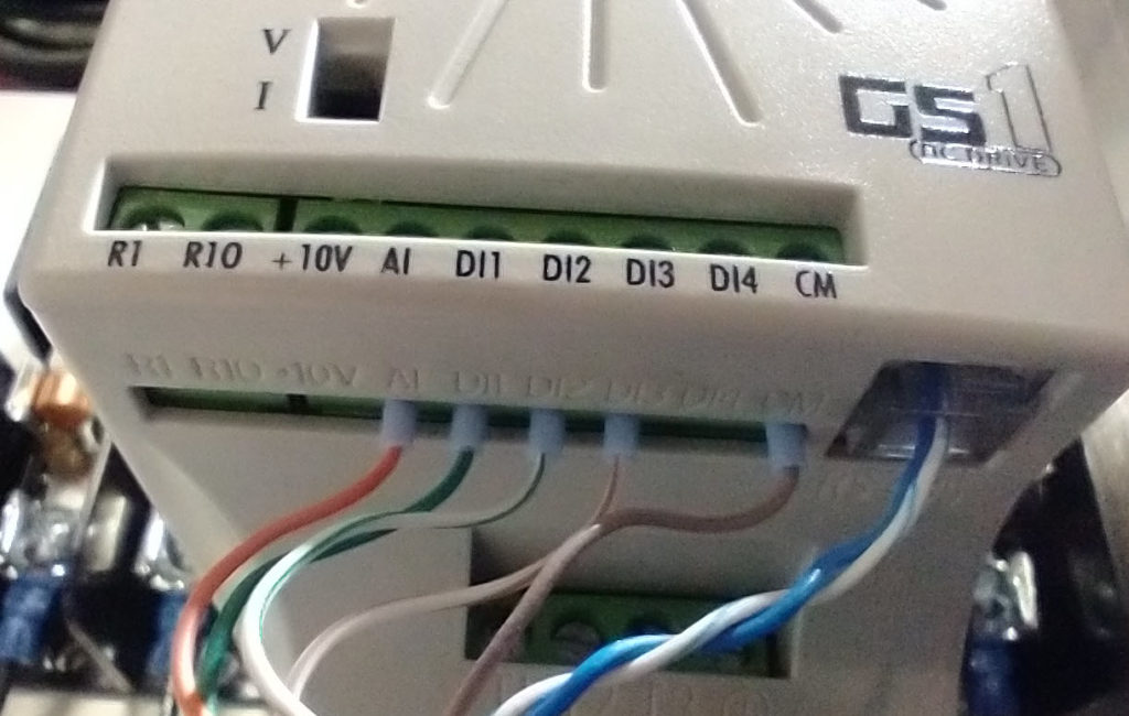
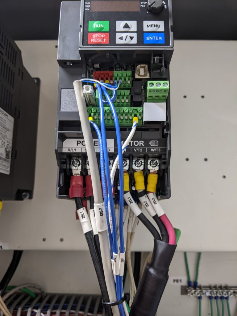
Original wiring should look similar to this.
New wiring needs to look like this.
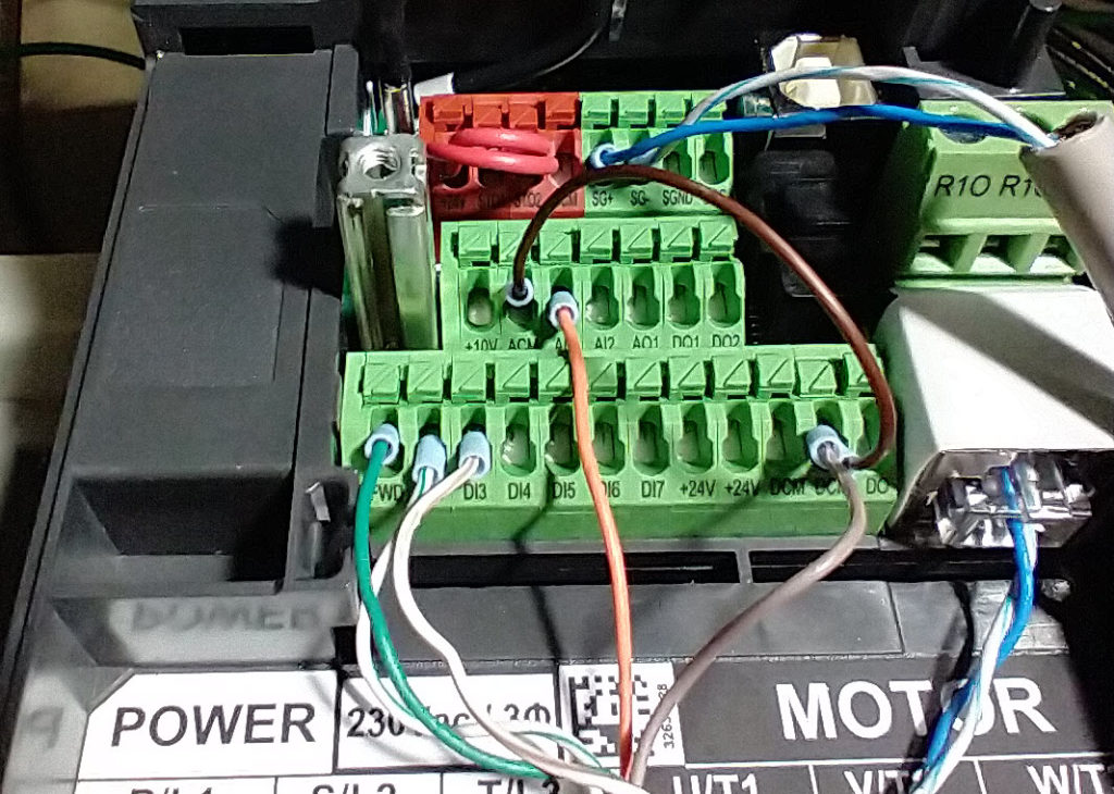
  GS1/2 wiring  ——  GS20 wiring
  A1I orange  ——— AI1 orange
  DI1 green  ———   FWD green
  DI2 white-green — REV white-green
  DI3 white-brown — DI3 white-brown
  CM brown ———   DCM & ACM brown
GS20 Blade Motor Drive Wiring
# is the drive number
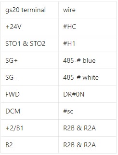
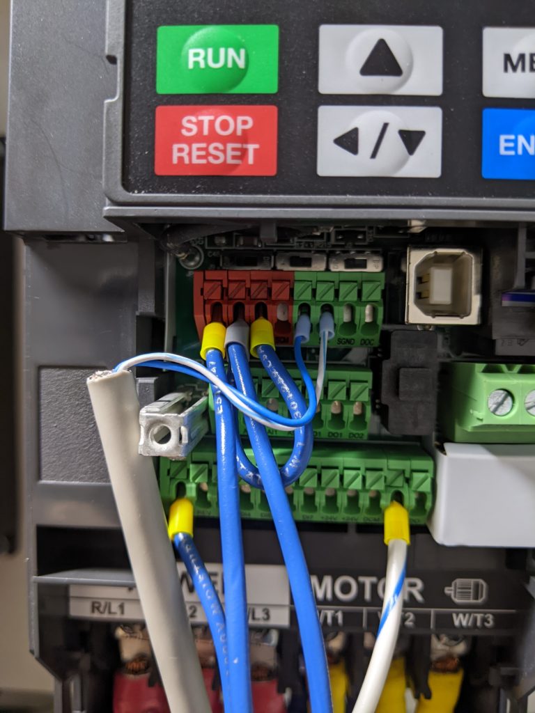
STO1 & STO2 should be jumped together
There are 2 sets of R2B & R2A, each goes to a set of braking resistors.
Confirm the Result
After checking all connections and reinstalling covers, restore power through the approved startup procedure. Confirm that the correct device comes online without a disconnected-drive or communication warning, then test its command, direction, and stopping response in a controlled mode.
If the issue remains, record the exact on-screen message, affected component, indicator-light state, and the last change made. Provide those details to Enventek Technical Support; do not repeatedly recalibrate or replace parts without identifying the cause.