Search for answers or browse our knowledge base.
Network Communications Overview
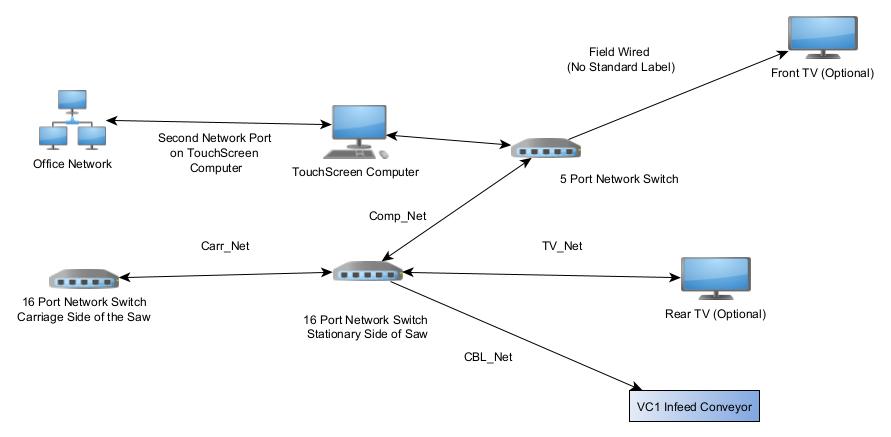
This document is provided to give you some general information about the saw’s internal network.
Network Diagram
The internal network is 10.1.1.1/24

IP Addresses
Note: Not all IP addresses are in use. Some devices are optional and may not be installed.
10.1.1.1 = CPU Touchscreen
10.1.1.4 = VC1 (V4) “Angle 1-V4”
10.1.1.5 = VC1 “Centerline 1-V5”
10.1.1.6 = VC1 “Angle 2-V6”
10.1.1.7 = VC1 “Centerline 2-V7”
10.1.1.8 = VC1 “Angle 6-V8”
10.1.1.9 = VC1 “Centerline 6-V9”
10.1.1.12 = VC1 “Left Horiz-V12”
10.1.1.13 = VC1 “Left Mat-V13”
10.1.1.20 = VC1 “Angle 3-V20”
10.1.1.21 = VC1 “Centerline 3-V21”
10.1.1.22 = VC1 “Angle 4-V22”
10.1.1.23 = VC1 “Centerline 4-V23”
10.1.1.24 = VC1 “Angle 5-V24”
10.1.1.25 = VC1 “Centerline 5-V25”
10.1.1.26 = VC1 “Right Horiz-V26”
10.1.1.28 = VC1 “Carriage-V28”
10.1.1.29 = VC1 “Right Mat-V29”
10.1.1.40 = VC1 “Conv A-V40”
10.1.1.45 = SER “Inker RS485 Ethernet converter”
10.1.1.200 = CPU “Front TV Display”
10.1.1.201 = CPU “Rear TV Display”
Labeled Cables
Comp_Net network cable
The communication to the touchscreen travels through the comp_net network cable. There is a 5 port network switch in the touchscreen panel which the saw computer connects to. That same switch is normally used for the front touchscreen however some customers run back to the stationary network switch depending on their situation.
Carr_Net network cable
The communication across the saw is done with an ethernet cable. It travels from port 1 or 2 in the network switch on the stationary side of the saw to port 1 or 2 in the carriage side of the saw.
If there are communication issues across the saw this could be the issue if it was damaged or disconnected.
TV_Net network cable
The Rear TV has a dedicated network cable that is labeled TV_Net
CBL_Net network cable
The CBL_Net cable travels to the infeed conveyor for the component saw.
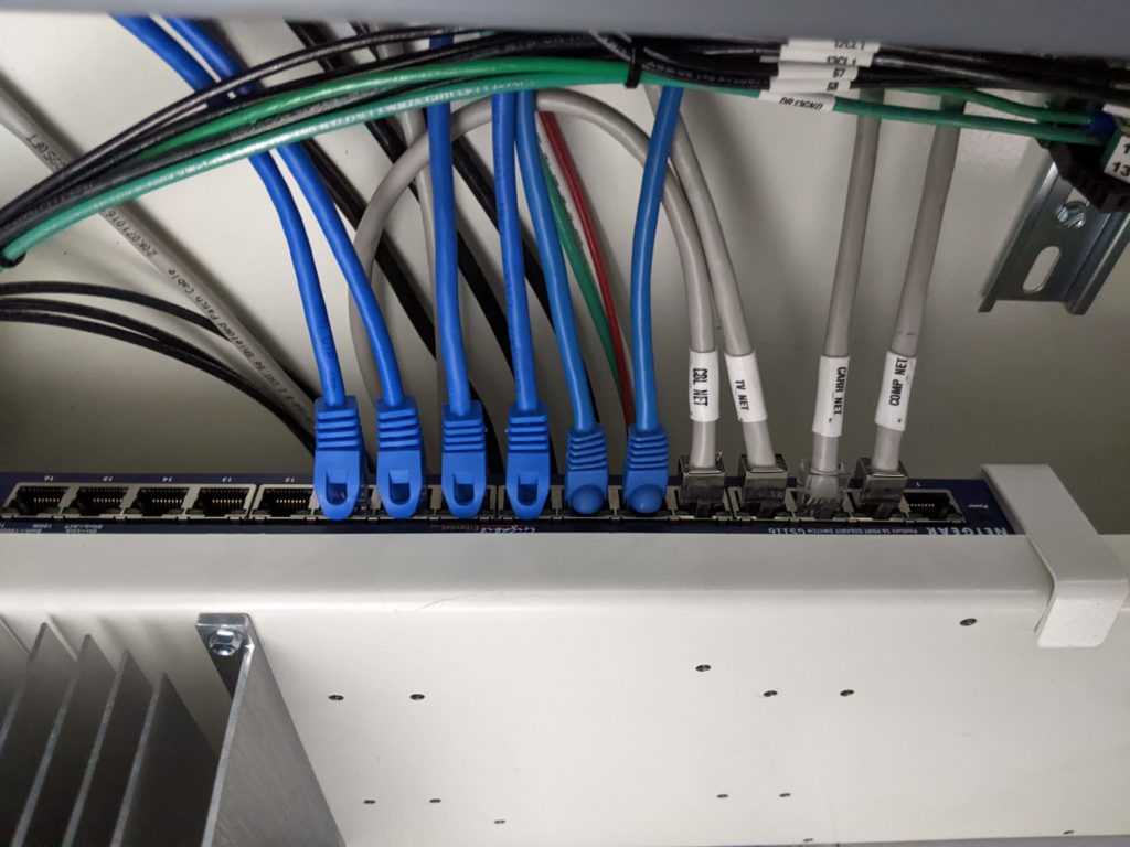
Stationary Network
The (Blue) wires connect each of the head’s VC1s on the stationary side to the network switch.
The (Gray) CBL Net cable connects to the “Smart Conveyor” (infeed conveyor).
The (Gray) TV_Net cable connects to the “rear tv” that is mounted on the rearguard.
The (Gray) Carr_Net cable connects the stationary side of the saw with the carriage side of the saw. This cable runs from switch to switch.
The (Gray) Comp_Net cable connects with the network switch located inside the touchscreen enclosure.

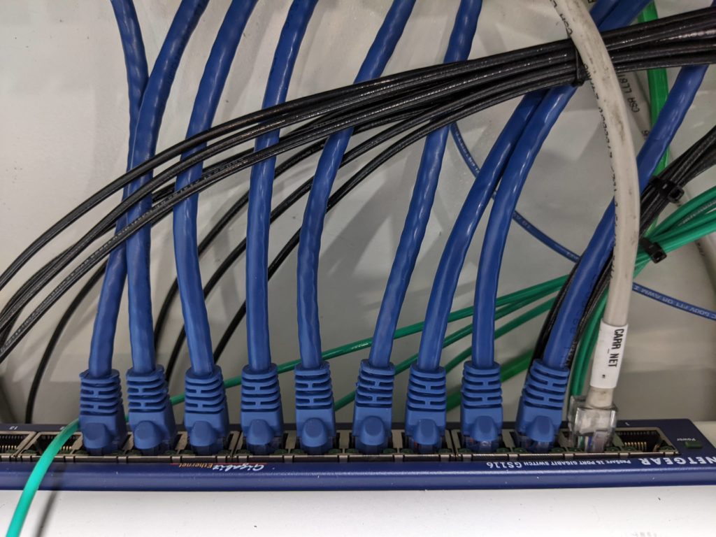
Carriage Side
The (Blue) wires connect each of the head’s VC1s on the carriage side to the network switch.
The (Gray) Carr_Net cable connects the carriage side of the saw with the stationary side of the saw. This cable runs from switch to switch.
