Search for answers or browse our knowledge base.
-
Retro C
-
-
- Articles coming soon
-
- How to Replace the Retro C's Computer
- Configuring the Touchscreen Computer's "Power-On"
- How to replace micro USB on the display computers
- How To: Transfer Files to the Retro C
- How to replace the USB hard drive on the touch screen computer
- New computer set bios power on
- Old computer set bios to power on
- TouchScreen Flip / Mirror Issue
-
-
-
- Stuck Angle or Centerline - How to Recover & Recalibrate
- Replacing an Angle Encoder
- Angle movements over run when going to position.
- Angle (Arch) Movements - Overview
- Angle Chains - Proper Chain Tension
- Diagnosing Unknown Noises Coming from Blade Motor
- Pivot Point Check
- Power or Wiring Troubleshooting for Angle Motors or VFDs
-
- Stuck Angle or Centerline - How to Recover & Recalibrate
- How To: Calibrate Centerline 1-5
- How To: Calibrate Centerline 1-5 (Advanced)
- Centerline (Vertical) Movements - Overview
- Replacing a Centerline Encoder
- Replacing a Centerline Gearbox
- Checking the Centerline Maximum & Minimum (Max & Min) Height Setting
- How to Tighten the Centerline Slides
- How To: Tension The Centerline Chains
-
-
-
- Common Retro C issues and solutions
- Countdown Timer / E-Stop Troubleshooting
- Scrap Belt or Scrap Incline VFD Disconnected: Troubleshooting
- Stuck Angle or Centerline - How to Recover & Recalibrate
- TouchScreen Flip / Mirror Issue
- Troubleshooting: Encoder Unplugged Error
- Troubleshooting: The Stationary or Carriage Side Horizontals Won't Move Anymore
-
-
Linear Pickline
-
Plant One Projection
-
SmartConveyor
-
Sticker Printer
Front Conveyor Sensor
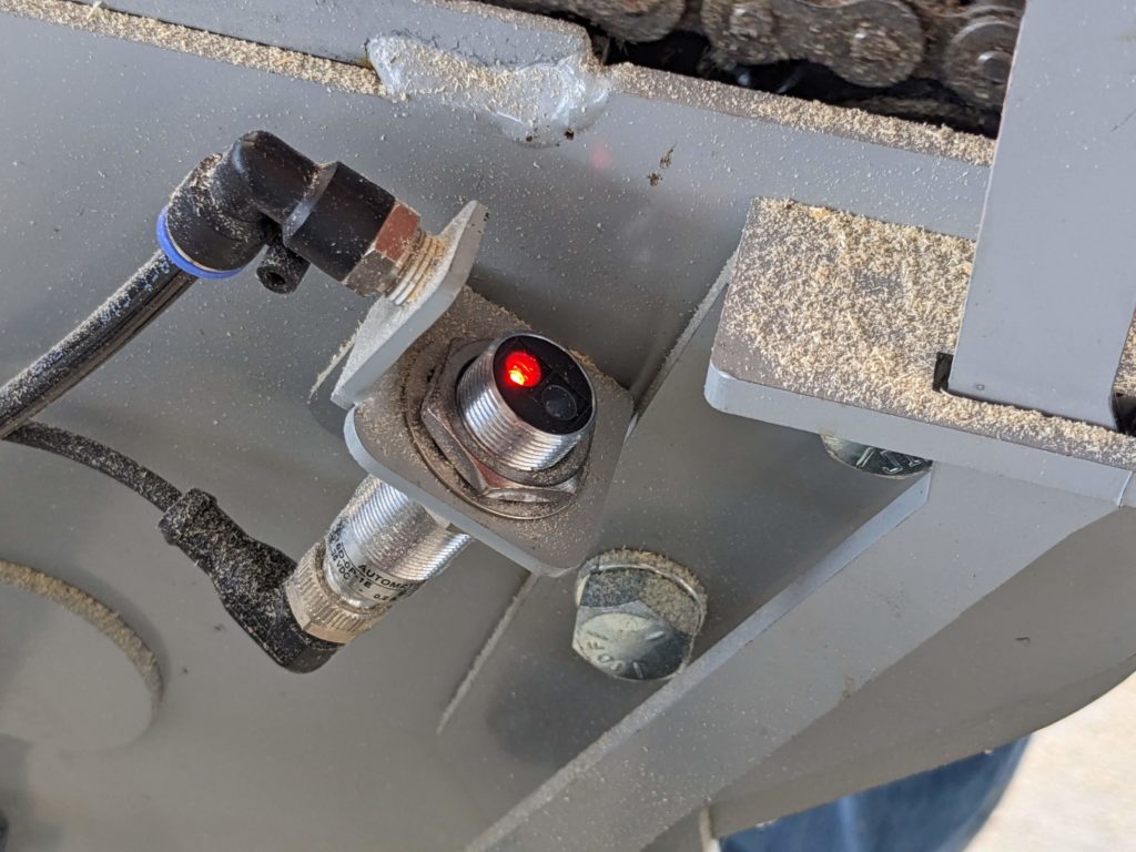
The Front Conveyor sensor is utilized on both the SmartConveyor and the front conveyor of the Linear Pickline. Additionally this sensor is the same one as the Retro C entry sensor.

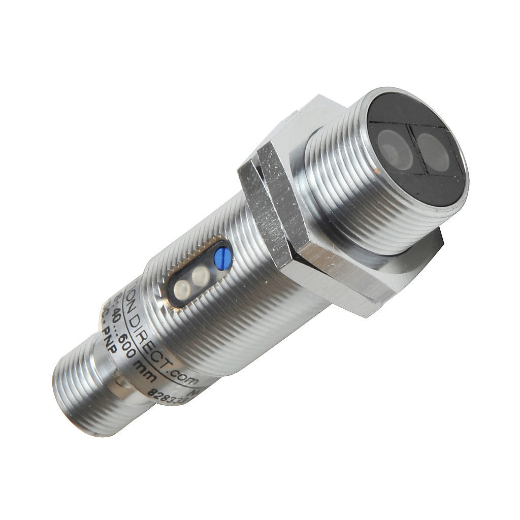
To determine whether the sensor is turned on, check if both lights are illuminated. When both lights are on, the sensor is activated.
A tuning dial is provided to adjust the sensor’s sensitivity to distance. The objective is to set the sensor to detect objects up to the height of a 2×4. You can test this by placing your hand over the sensor and using a small screwdriver to adjust the (Blue) (see image below) dial until the green light on the sensor comes on (by waving your hand over it) at the desired height.

The sensor’s status can be observed on the Check screens of the software. The lights will indicate whether the sensor is active or not.
To ensure accurate detection of the front of the board when the Lumber stop is raised, it is crucial to adjust the sensor’s angle. Follow the steps below to perform this adjustment:
- Locate the easily accessible and visible bolt that secures the sensor in place.
- Use an appropriate tool, such as a wrench or screwdriver, to loosen the bolt, allowing for adjustment.
- Carefully adjust the angle of the sensor until it is positioned correctly to detect the front of the board when the Lumber stop is raised.
- Take care to align the sensor precisely, ensuring it is neither too high nor too low for accurate detection.
- Once the desired angle is achieved, securely tighten the bolt. Be cautious not to overtighten, as it may damage the sensor or its mounting.
- Test the conveyor system by operating it with the Lumber stop in the raised position. Verify that the sensor consistently and reliably detects the front of the board.
- If necessary, repeat the adjustment process to fine-tune the sensor angle for optimal performance.
By following these steps, you will be able to effectively adjust the sensor angle, ensuring accurate detection of the front of the board when the Lumber stop is raised.