How Can We Help?
Search for answers or browse our knowledge base.
-
Retro C
-
-
- Articles coming soon
-
- How to Replace the Retro C's Computer
- Configuring the Touchscreen Computer's "Power-On"
- How to replace micro USB on the display computers
- How To: Transfer Files to the Retro C
- How to replace the USB hard drive on the touch screen computer
- New computer set bios power on
- Old computer set bios to power on
- TouchScreen Flip / Mirror Issue
-
-
-
- Stuck Angle or Centerline - How to Recover & Recalibrate
- Replacing an Angle Encoder
- Angle movements over run when going to position.
- Angle (Arch) Movements - Overview
- Angle Chains - Proper Chain Tension
- Diagnosing Unknown Noises Coming from Blade Motor
- Pivot Point Check
- Power or Wiring Troubleshooting for Angle Motors or VFDs
-
- Stuck Angle or Centerline - How to Recover & Recalibrate
- How To: Calibrate Centerline 1-5
- How To: Calibrate Centerline 1-5 (Advanced)
- Centerline (Vertical) Movements - Overview
- Replacing a Centerline Encoder
- Replacing a Centerline Gearbox
- Checking the Centerline Maximum & Minimum (Max & Min) Height Setting
- How to Tighten the Centerline Slides
- How To: Tension The Centerline Chains
-
-
-
- Common Retro C issues and solutions
- Countdown Timer / E-Stop Troubleshooting
- Scrap Belt or Scrap Incline VFD Disconnected: Troubleshooting
- Stuck Angle or Centerline - How to Recover & Recalibrate
- TouchScreen Flip / Mirror Issue
- Troubleshooting: Encoder Unplugged Error
- Troubleshooting: The Stationary or Carriage Side Horizontals Won't Move Anymore
-
-
Linear Pickline
-
Plant One Projection
-
SmartConveyor
-
Sticker Printer
< All Topics
Print
Conveyor Encoder V40
Updated
Encoder wire route
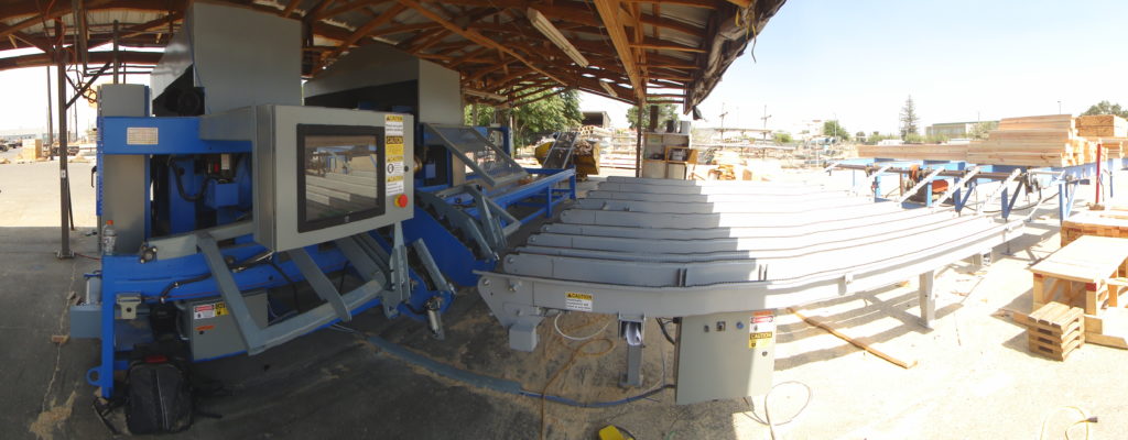
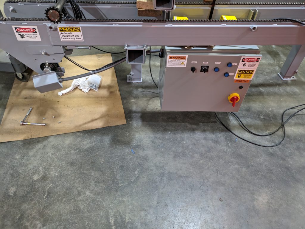
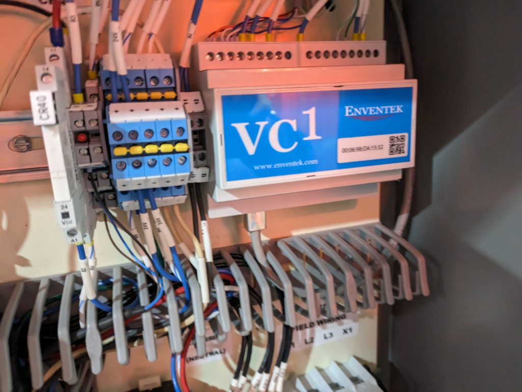
The Conveyor encoder is located at the end of the shaft of the conveyor. The encoder wire travels through liquid tight to the conveyor panel and enters into the VC1. See below for the route of the encoder. The encoder may require replacement or the cable.
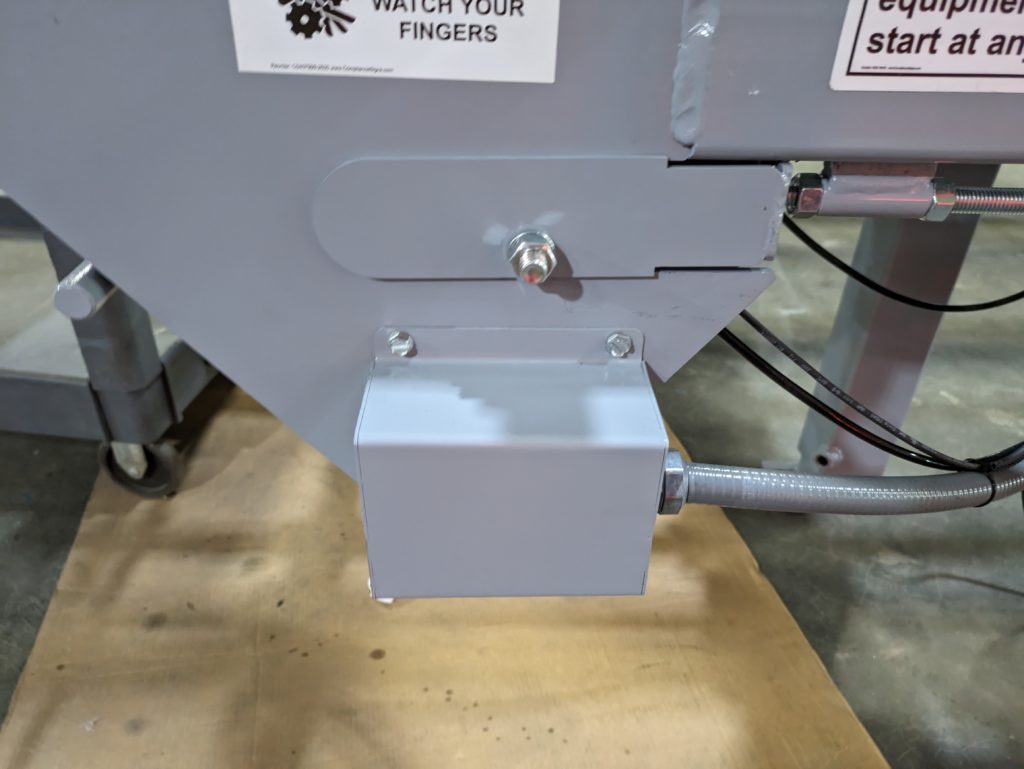
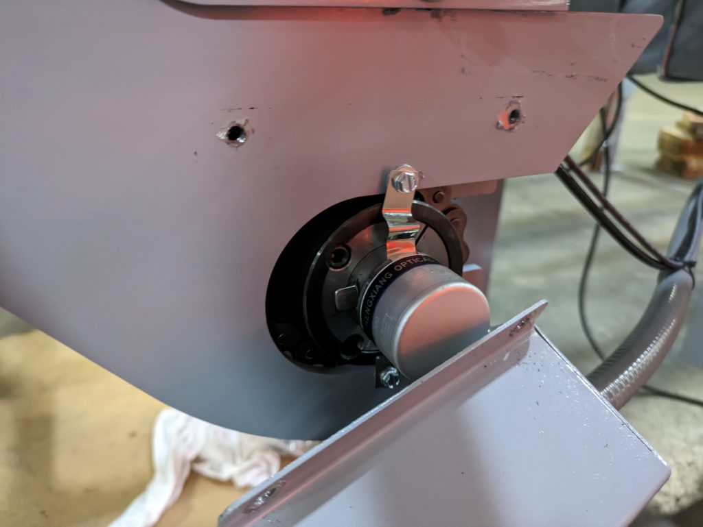

Slide The encoder on to the shaft and clamp it down with the socket cap bolt. Then add the screws back to the flanges to mount them.

The wiring enters into the conveyor electrical box and directly connects to the VC1 with a RJ45 connector.
Lights indicate that it is properly plugged in.
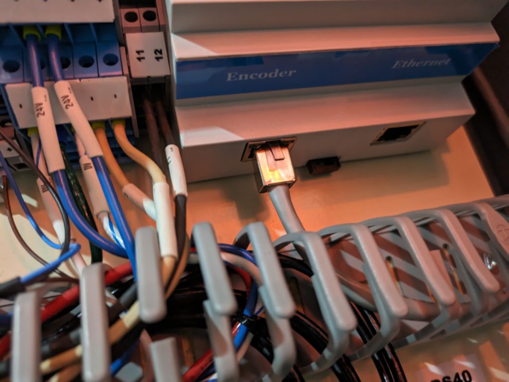
Table of Contents