Search for answers or browse our knowledge base.
-
Retro C
-
-
- Articles coming soon
-
- How to Replace the Retro C's Computer
- Configuring the Touchscreen Computer's "Power-On"
- How to replace micro USB on the display computers
- How To: Transfer Files to the Retro C
- How to replace the USB hard drive on the touch screen computer
- New computer set bios power on
- Old computer set bios to power on
- TouchScreen Flip / Mirror Issue
-
-
-
- Stuck Angle or Centerline - How to Recover & Recalibrate
- Replacing an Angle Encoder
- Angle movements over run when going to position.
- Angle (Arch) Movements - Overview
- Angle Chains - Proper Chain Tension
- Diagnosing Unknown Noises Coming from Blade Motor
- Pivot Point Check
- Power or Wiring Troubleshooting for Angle Motors or VFDs
- Dirty Slide
-
- Stuck Angle or Centerline - How to Recover & Recalibrate
- How To: Calibrate Centerline 1-5
- How To: Calibrate Centerline 1-5 (Advanced)
- Centerline (Vertical) Movements - Overview
- Replacing a Centerline Encoder
- Replacing a Centerline Gearbox
- Checking the Centerline Maximum & Minimum (Max & Min) Height Setting
- How to Tighten the Centerline Slides
- How To: Tension The Centerline Chains
-
-
-
- Common Retro C issues and solutions
- Countdown Timer / E-Stop Troubleshooting
- Scrap Belt or Scrap Incline VFD Disconnected: Troubleshooting
- Stuck Angle or Centerline - How to Recover & Recalibrate
- TouchScreen Flip / Mirror Issue
- Troubleshooting: Encoder Unplugged Error
- Troubleshooting: The Stationary or Carriage Side Horizontals Won't Move Anymore
-
-
Linear Pickline
-
Plant One Projection
-
SmartConveyor
-
Sticker Printer
Sticker Printer – Peel Off Sensor Adjustment
Occasionally the peel off sensor will not be in the right “alignment” and no matter what you do, the peel off sensor will say that something is covering it and it won’t spit out another sticker. To fix this issue you will need to follow these steps:
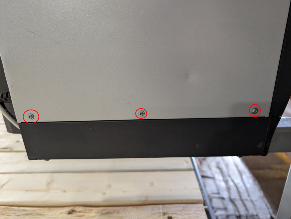
Step 1: Remove the cover side cover of the sticker printer by removing the three screws in the picture below.
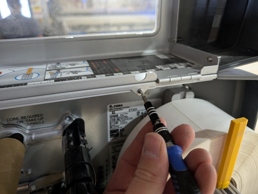
Step 2: Remove the one screw that is under the flip up door on the others side of the printer.
Step 3: Now the whole cover can be removed
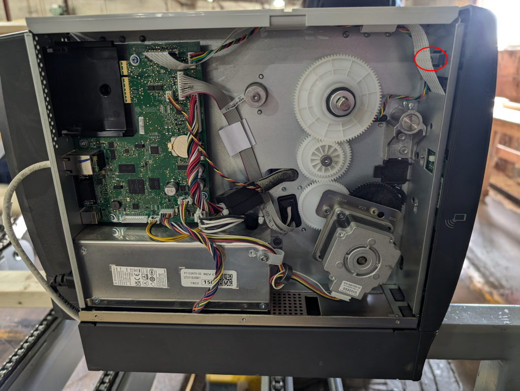
Step 4: With the cover off locate the screw that is circled in red below which will allow the front plastic piece and LCD screen to tilt forward and be removed. Take it out.
Step 5: Loosen the four screws circled in red below and then rotate the whole green PCB clockwise as much as you can (admittedly this won’t be much) and retighten the screws. In every case we have seen, the green PCB needs to be rotated about 1/16″ so that the sensor isn’t shooting too high.
Step 6: Put everything back the way it was, using all the screws.