Search for answers or browse our knowledge base.
Emergency Stop System — Overview & Diagnostic Guide
This guide explains how the Emergency Stop (E-Stop) system works and how to diagnose common issues when the machine will not run.
The Emergency Stop system operates as a continuous +24 VDC safety loop. If either of the two +24 VDC wires are broken anywhere in the system, the machine will immediately go into an Emergency Stop condition.
Emergency Stop Safety Relay (Main Control Point)
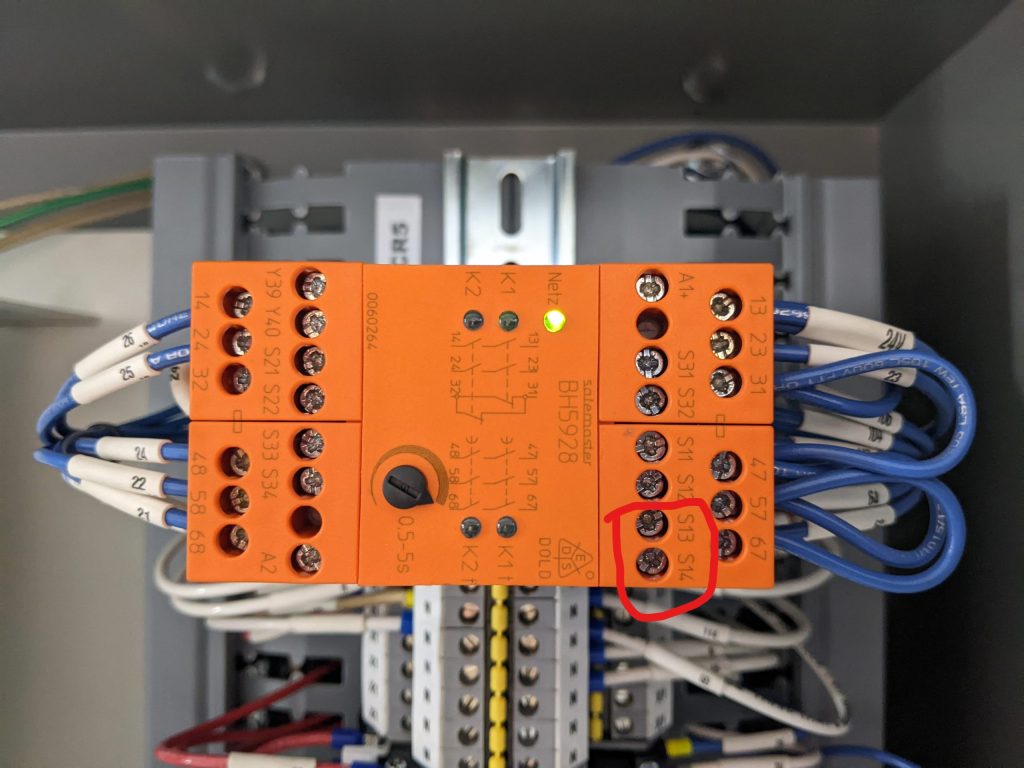
This is the primary Emergency Stop safety relay.
- The emergency stop circuit starts at terminal S11.
- There must be 24–27 VDC between terminals A1 and A2.
- The relay indicator light must be ON for normal operation.
- The emergency stop signal returns to this relay at terminals S31 and S32.
If this relay is not powered, the entire machine will remain in Emergency Stop.
Schematic

Legend for Wiring Diagram
Green labels indicate the wire numbers.
Squares indicate the red terminals on the stationary side of the saw they are numbered 70-76.
Teal text indicates terminal labels printed on terminal blocks or components.
Emergency Stop Signal Path (In Order)
- The emergency stop circuit starts at S11 on the emergency stop relay.
This relay requires VC1 Output 7 to be ON so the software can safely stop the system if a fault is detected. - There must be 24–27 VDC between A1 and A2 on the emergency stop relay.
The indicator light on the relay should be ON when power is present. - The signal then travels to the air pressure safety sensor (CR27).
This sensor requires at least 75 PSI of air pressure for the machine to operate.
If air pressure drops below 75 PSI, the machine will immediately go into Emergency Stop. - From the air pressure sensor, the signal goes to the cable pull emergency stop (PB10),
which runs around the saw. - From the cable pull, it goes to the touchscreen emergency stop (PB11).
- From the touchscreen emergency stop, it goes to the safety key lockout/tagout switch (PB12).
- Finally, the signal returns to the emergency stop relay at terminals S31 and S32 (orange wires).
E-Stop Terminals

Emergency Stop Terminals – Stationary Electrical Panel
The emergency stop terminals are located in the top right of the stationary electrical panel.
When the emergency stop is NOT active:
- Terminals 70 through 76 should each read between 24 and 27 VDC.
- There should also be electrical continuity from terminal 70 through terminal 76.
If voltage is missing at one terminal, the emergency stop circuit is broken between the last terminal that has voltage and the first terminal that does not.
This allows you to isolate which device is causing the fault.
Pneumatic Sensor
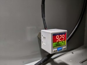

Pneumatic (Air Pressure) Safety Sensor – CR27
This sensor verifies that there is enough air pressure for the machine to operate safely.
- Minimum required pressure: 75 PSI
- If air pressure drops below 75 PSI, the system will immediately enter Emergency Stop.
- The indicator light on CR27 should be ON when air pressure is sufficient.
Cable Pull Emergency Stop
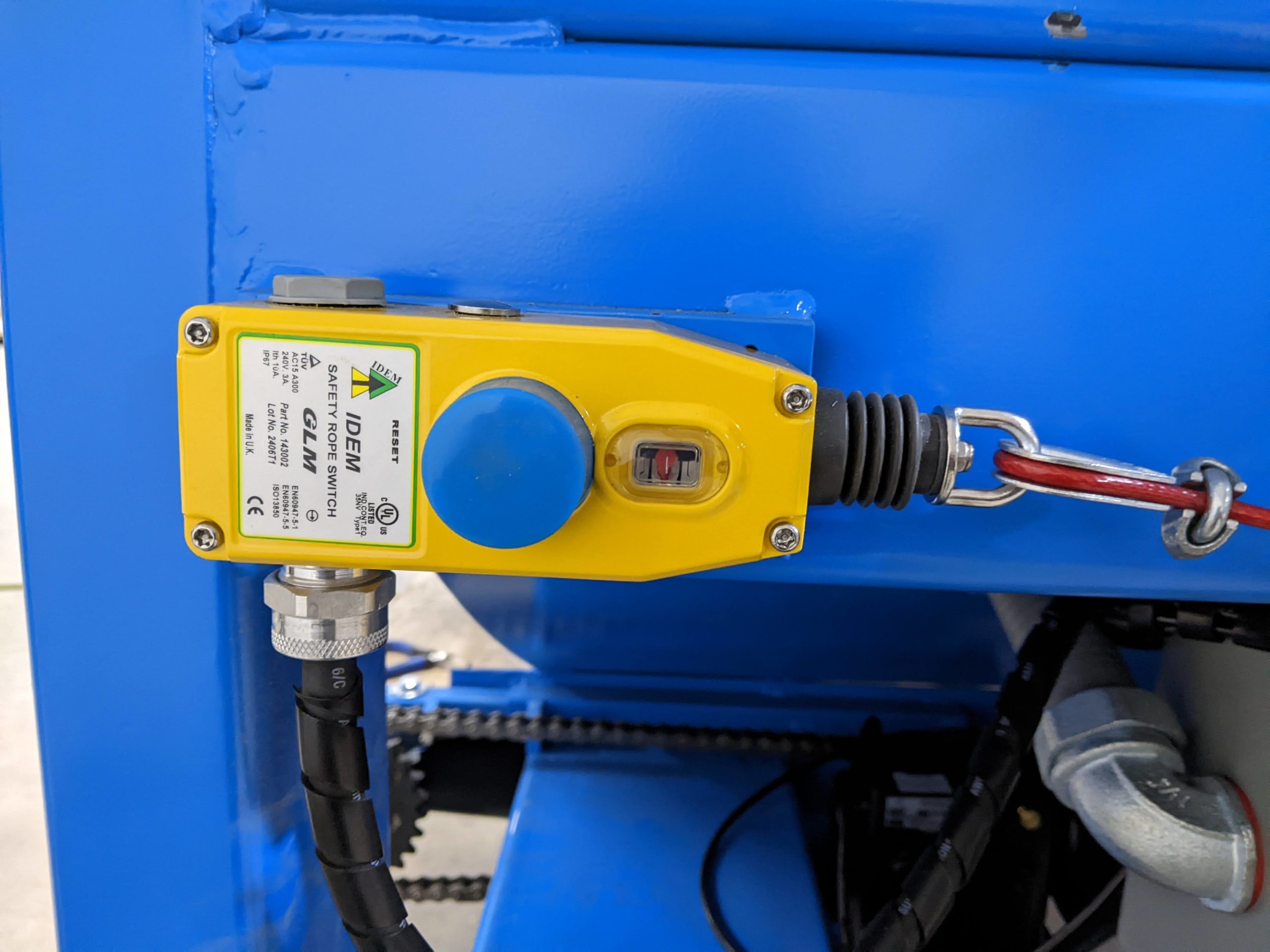
Cable Pull Emergency Stop – PB10
The cable pull runs around the perimeter of the saw to provide emergency stop protection along the entire machine.
For the machine to run:
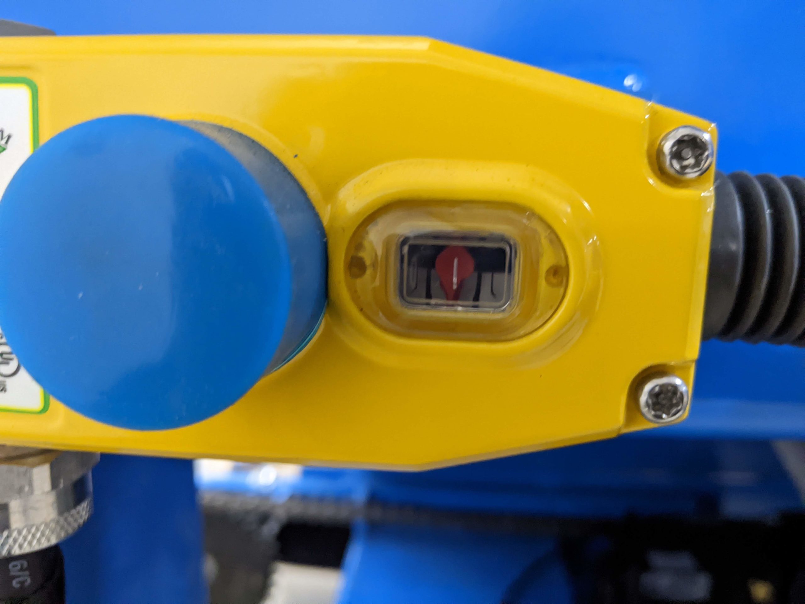
- The indicator must be centered on the switch.
- The cable must not be too tight or too loose.
If the cable is pulled, broken, too tight, or too loose, the emergency stop circuit will open and stop the machine.
Touchscreen Emergency stop switch
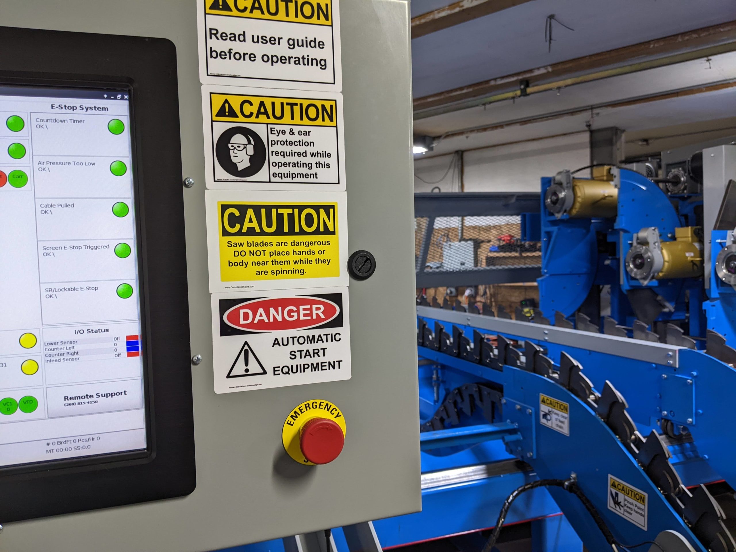
Touchscreen Emergency Stop – PB11
This functions the same as a physical emergency stop button.
When pressed, it opens the emergency stop circuit and stops the machine.
It must be fully released before the system can be reset.
Safety Key Emergency stop switch
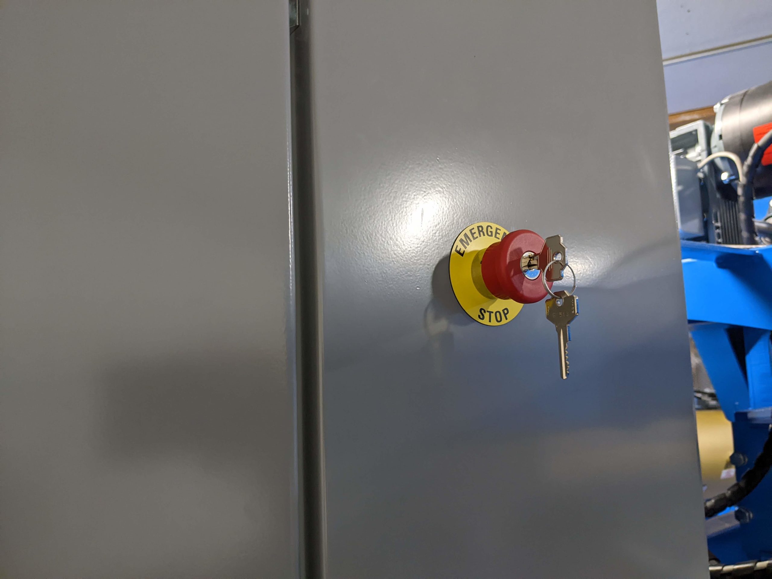
Safety Key Emergency Stop – PB12 (Lockout/Tagout)
This switch is used for lockout/tagout during maintenance.
When the switch is pressed and the key is removed:
- The machine cannot be restarted.
- The emergency stop remains active until the key is reinserted and turned.
Each facility should still follow its own official lockout/tagout procedures.